
Gas liquefying plant

Active Publication Date: 2006-07-13
JGC CORP
View PDF7 Cites 8 Cited by
  • Summary
  • Abstract
  • Description
  • Claims
  • Application Information

AI Technical Summary

Benefits of technology

[0016] The present invention addresses the above-mentioned problems, and an object thereof is to provide a gas liquefaction plant which solves the disadvantages of prior-art gas liquefaction plants. With gas liquefaction plant of the present invention, it is possible to reduce the height of a pipe rack, to solve the issue of the strength of the pipe rack, to shorten the design and construction period of the pipe rack so as to reduce the construction cost. In addition, it is possible to reduce high elevation work so that the risk related to the construction is reduced, and to solve the issue of heat loss and pressure drop of a refrigerant.

Problems solved by technology

That results in a prolonged construction period and increased construction cost.
Moreover, since the higher pipe rack requires more high elevation work, the risk related to the construction increases and safety issues may occur.
Furthermore, heat loss and pressure drop of the refrigerant may increase since the refrigerant piping lines become long.

Method used


Image

  • Gas liquefying plant
  • Gas liquefying plant
  • Gas liquefying plant

Examples


Embodiment Construction

[0035] Preferred embodiments of the invention will be described with reference to the drawings. However, it should not be construed that the present invention is limited to those embodiments; rather, components of those embodiments, for example, may be combined if necessary.

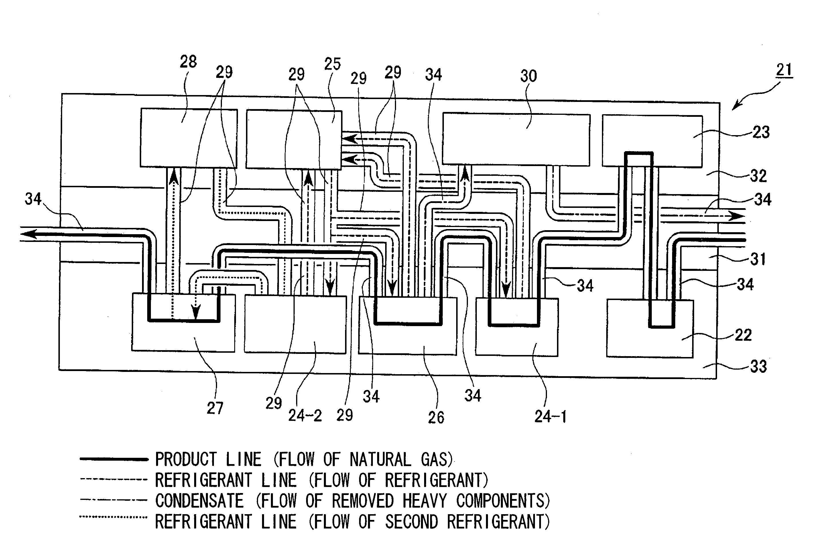
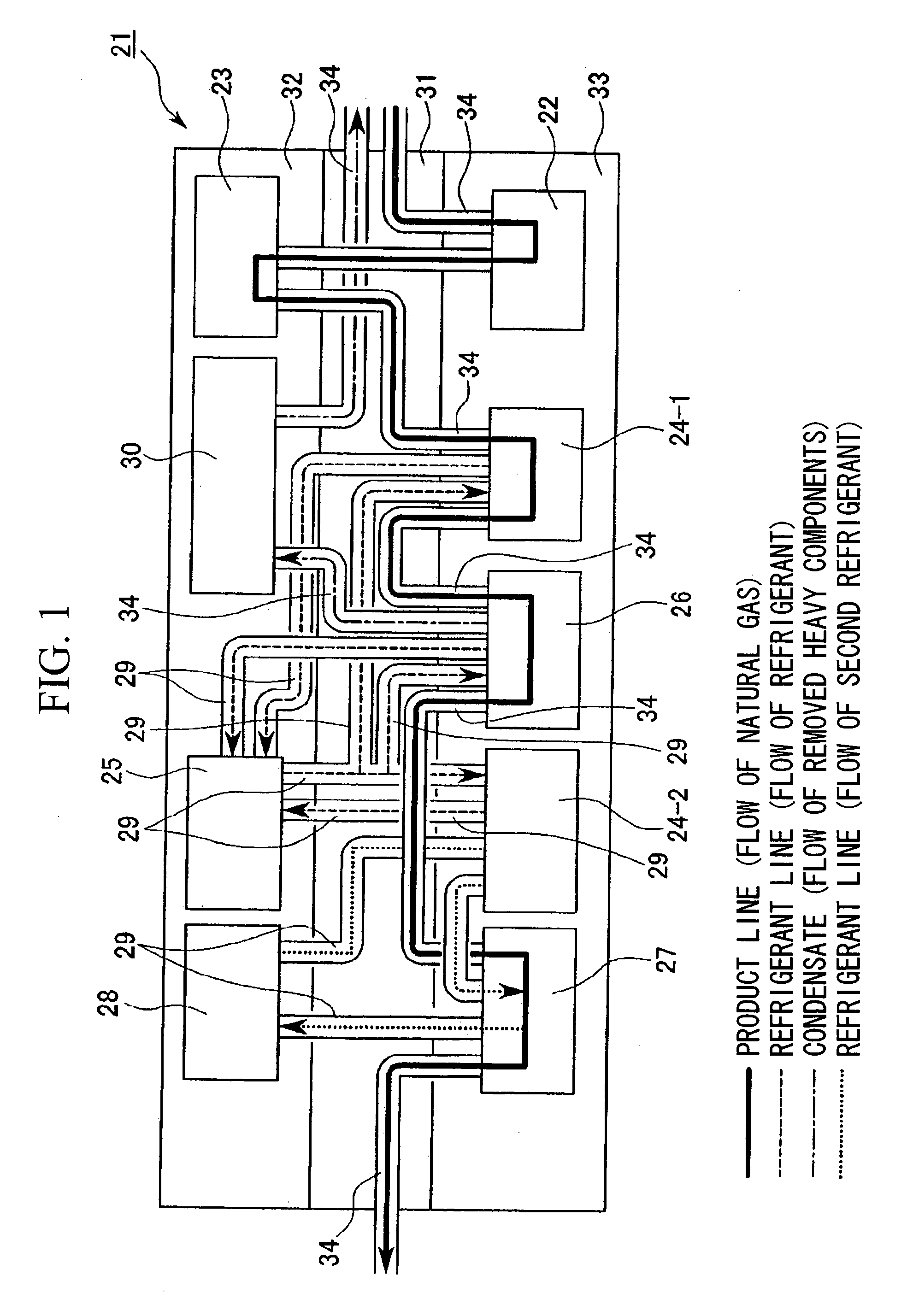
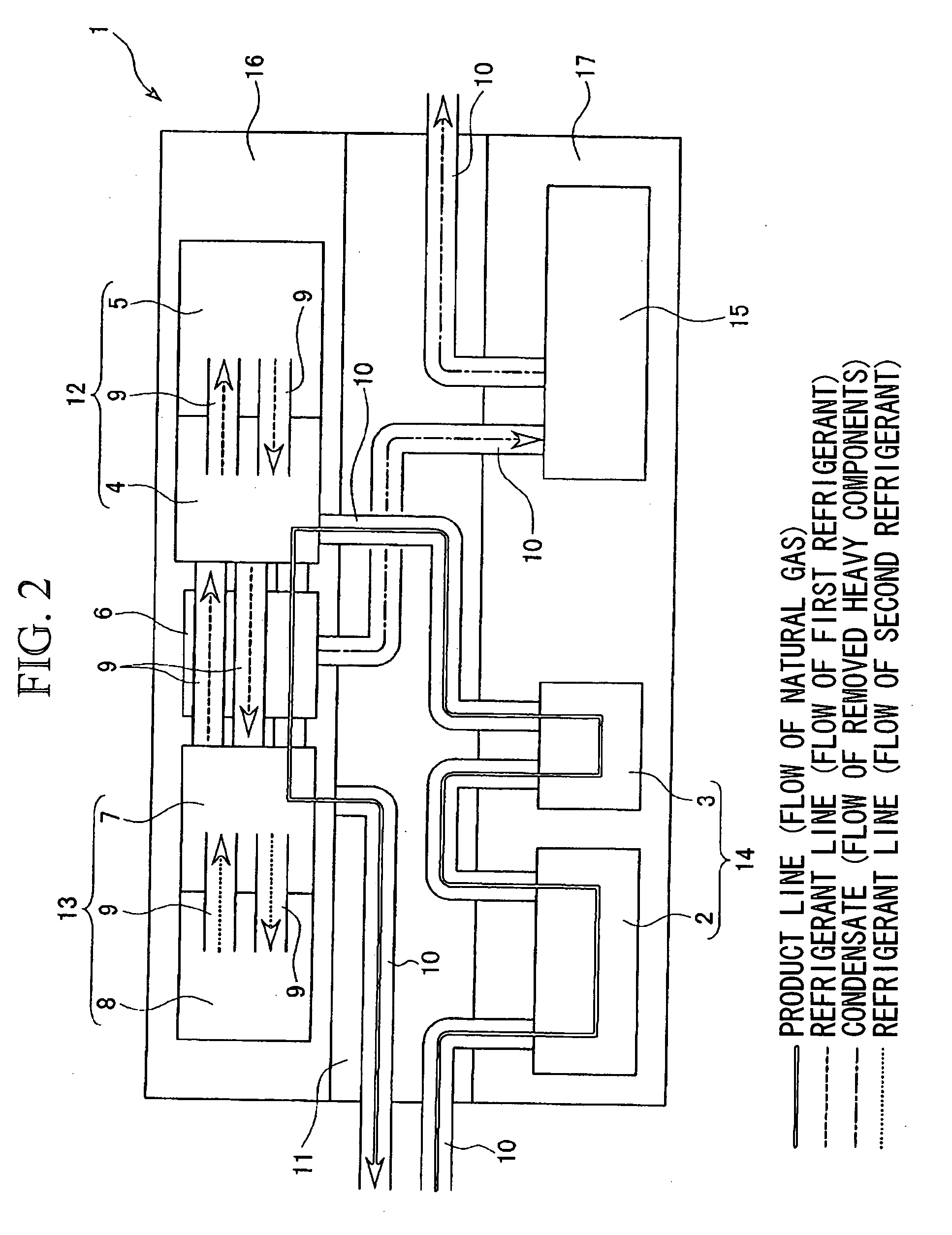
[0036] A gas liquefaction plant 1 according to an embodiment of the present invention will be described with reference to FIG. 2.

[0037] Feed gas used in the gas liquefaction plant 1 according to this embodiment of the present invention is natural gas, for example.

[0038] First, as a pre-treatment of the natural gas, acid gases are removed from the natural gas by an acid gas removal facility 2, and then the natural gas is dehydrated in a dehydrating facility 3. Upon removal of acid gasses, CO2 and H2S, are removed, for example, and upon dehydration, contaminants, such as mercury or mercury-containing compounds, are also removed.

[0039] Next, the pre-treated natural gas is supplied to a pre-cooling exchanger 4, i...


PUM


Abstract

A gas liquefaction plant includes a pre-cooling exchanger which pre-cools a feed gas by means of indirect heat exchange with a first refrigerant; a first refrigerant compressor which compresses the first refrigerant which has been used for refrigerating the feed gas in the pre-cooling exchanger; a cryogenic heat exchanger which refrigerates and liquefies the feed gas which has been pre-cooled by the pre-cooling exchanger by means of indirect heat exchange with a second refrigerant; a second refrigerant compressor which refrigerates the second refrigerant which has been used for cooling and liquefying the feed gas in the cryogenic heat exchanger; and a piping complex which receives piping used in the gas liquefaction plant, wherein the pre-cooling exchanger, the first refrigerant compressor, the cryogenic heat exchanger, and the second refrigerant compressor are installed at one side of the piping complex.

Description

TECHNICAL FIELD [0001] The present invention relates to a gas liquefaction plant in which feed gas, such as natural gas, is liquefied to yield liquefied gas, such as liquefied natural gas. [0002] Priority is claimed on Japanese Patent Application No. 2003-387748, filed Nov. 18, 2003, the content of which is incorporated herein by reference. DESCRIPTION OF THE RELATED ART [0003] Conventionally, gas liquefaction plants in which a natural gas, as a feed gas, is liquefied to obtain a liquefied natural gas have been known, and such a gas liquefaction plant includes: a pre-cooling facility which pre-cools a natural gas and refrigerates a blended refrigerant (MCR) which is used for pre-cooling the natural gas; and a liquefaction facility which liquefies the pre-cooled natural gas and refrigerates the blended refrigerant which is used for liquefying the pre-cooled natural gas (see U.S. Pat. No. 6,119,479, for example). [0004] Such a gas liquefaction plant 21 according to the prior art will ...

Claims


Application Information

Patent Timeline
IPC IPC(8): F25J1/00F25B7/00F25J1/02F25J3/02
CPCF25J1/0022F25J1/0214F25J1/0258F25J1/0259
Inventor LIJIMA, TAKAYUKIFUKUOKA, SHINICHITAKEZAWA, NAOYUKI
Owner JGC CORP
Features
  • Generate Ideas
  • Intellectual Property
  • Life Sciences
  • Materials
  • Tech Scout
  • Unparalleled Data Quality
  • Higher Quality Content
  • 60% Fewer Hallucinations
Learn More