Respiration-synchronous gas supplying device

a gas supply device and synchronization technology, applied in the direction of valve operating means/release devices, applications, diagnostic recording/measuring, etc., can solve the problems of unnecessary supply of oxygen, waste of oxygen, user discomfort, etc., and achieve the effect of reducing nois

Active Publication Date: 2006-07-13
TEIJIN LTD
View PDF0 Cites 50 Cited by
  • Summary
  • Abstract
  • Description
  • Claims
  • Application Information

AI Technical Summary

Benefits of technology

[0009] As a result of much diligent research direction toward solving the problems described above, the present inventors have discovered that by providing means for recognizing the inspiration phase initial point and the expiration phase initial point of the user, and preventing recognition of the initial point of the next inspiration phase during the time between recognition of the inspiration phase initial point and recognition of the expirati

Problems solved by technology

However, when such respiration phase detection means is used to recognize the inspiration phase initial point, it sometimes occurs that areas within the inspiration phase other than the inspiration phase initial point, or periods of variation in the respiratory signal due to vibration or wind are erroneously recognized as the inspiration phase initial point, which can result in unnecessary supply of oxygen.
Such unnecessary supply of oxygen not only wastes the oxygen but also produces a feeling of discomfort for the user.
However, since the respiratory cycle of a user varies from time to time and hour to hour, the method of setting a fixed period without recognizing the next inspiration phase initial point is not suitably adaptable to such variations in the respiratory cycle, and therefore areas within the inspiration phase other than the inspiration phase initial point are erroneously recognized as the inspiration phase initial point.
This results in supply of oxygen when it is not needed, or conversely, the inspiration phase initial point is missed, making it impossible to supply oxygen when it is needed.
However, since the respiration waveform size and rise up s

Method used


Image

  • Respiration-synchronous gas supplying device
  • Respiration-synchronous gas supplying device
  • Respiration-synchronous gas supplying device

Examples


examples

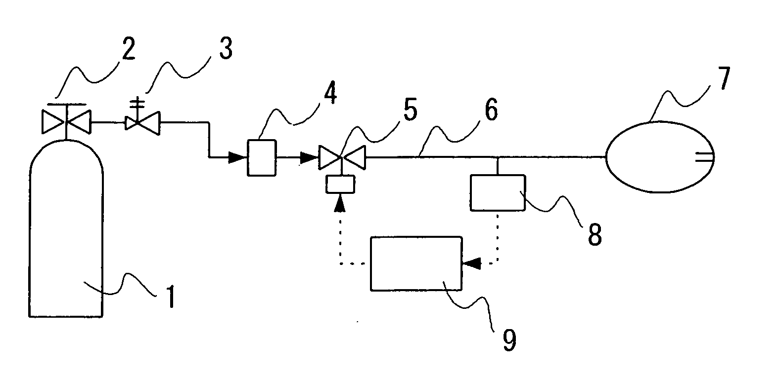
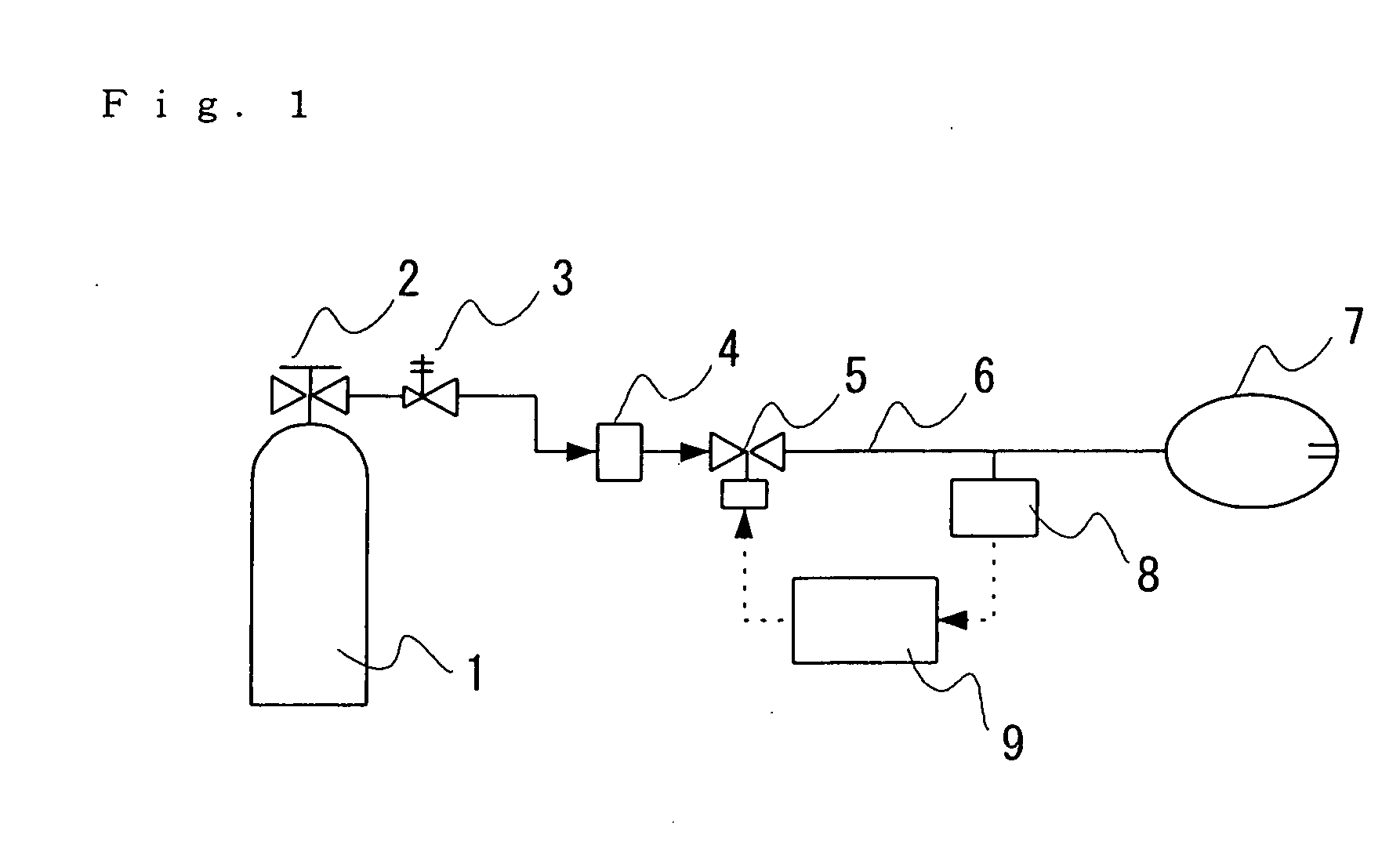
[0043]FIG. 1 is a schematic view of an embodiment of a respiratory gas supply unit of the invention. Specifically, the oxygen exiting the oxygen cylinder 1 as the respiratory gas generating means passes through a cylinder valve 2 and a pressure reduction valve 3, and then through conductor means 6 equipped with an orifice-type flow rate setting device 4 and an automatic on-off valve 5, and is emitted from a nasal canula 7 as the open supply means.

[0044] The pressure variation during respiration is converted to electrostatic capacity variation by respiration phase detection means 8 equipped with a diaphragm-type micropressure fluctuation sensor branching from the conductor means 6, and the signal is sent to control means 9.

[0045] The control means 9 converts the respiration phase data, opens the automatic on-off valve 5 at the moment in which the inspiration phase initial point is recognized, and calculates the open time of the automatic on-off valve 5, while keeping the automatic ...


PUM


Abstract

As a unit which functions to prevent variations in the respiration phases of a user, erroneous recognition due to disturbances such as vibrations of the supply unit and wind, discomfort to the user due to unnecessary supply of oxygen and wasteful supply of oxygen, there is provided a respiration-synchronizing gas supply unit characterized by comprising means for recognizing the inspiration phase initial point and the expiration phase initial point, and by carrying out automatic on-off valve control with recognition means that does not recognize the next inspiration phase initial point during the time between recognition of the inspiration phase initial point and recognition of the expiration phase initial point, and between recognition of the expiration phase initial point and elapse of a predetermined time period.

Description

TECHNICAL FIELD [0001] The present invention relates to a respiration-synchronizing gas supply unit provided with an automatic on-off valve capable of operating in synchronization with the respiratory cycle of a user. More specifically, the invention relates to a unit for intermittently supplying a therapeutic gas such as oxygen gas to a user in synchronization with the respiratory cycle. BACKGROUND ART [0002] A method of increasing the oxygen utilization efficiency for oxygen obtained from oxygen cylinders or oxygen-concentrated gas obtained from oxygen concentrators has been proposed, wherein the oxygen is supplied only during inspiration and supply is interrupted during expiration, in order to achieve synchronization with the patient's respiratory cycle and thereby prevent waste of the oxygen supply during expiration (Japanese Unexamined Patent Publication No. 59-8972). [0003] Devices which make use of this method include demand regulators provided with an automatic on-off valve ...

Claims


Application Information

Patent Timeline
IPC IPC(8): A61M16/00A62B7/00
CPCA61M2016/0021A61M16/00A61M16/024A61M16/101A61M16/204A61B5/0803A61M2016/0036A61M2230/42
Inventor MIZUTA, MAMIKONAWATA, HIDEO
Owner TEIJIN LTD
Why Eureka
Try Eureka