Spray device and method

a spray device and spray technology, applied in the direction of liquid transfer devices, single-unit apparatuses, pharmaceutical products, etc., can solve the problems of reducing the shelf life of mixtures, limiting the use of spray devices, and limiting the shelf life of liquid medicaments having a relatively long shelf life, so as to minimize the risk of cross contamination

Inactive Publication Date: 2006-07-13
BECTON DICKINSON & CO
View PDF5 Cites 17 Cited by
  • Summary
  • Abstract
  • Description
  • Claims
  • Application Information

AI Technical Summary

Benefits of technology

[0007] In one preferred embodiment, the longitudinal projection of the third stopper is resilient and the overall longitudinal length of the third stopper including the longitudinal projection is greater than the longitudinal length of the body portion of the spray nozzle. In this embodiment, the longitudinal projection of the third stopper is resiliently deformed against an internal surface of the central opening in the spray nozzle, such that the entire body portion of the third stopper is received in the body portion of the spray nozzle, establishing fluid communication between the tubular barrel and the spray nozzle port through the generally longitudinally extending internal groove. In another preferred embodiment, the internal surface of the central opening in the spray nozzle includes an annular rib adjacent the opening which sealingly engages an end portion of the longitudinal projection and the longitudinal projection further includes a reduced diameter neck portion, such that axial deformation of the longitudinal projection receives the annular rib in the reduced diameter neck portion of the longitudinal projection, establishing fluid communication around the longitudinal projection. In this embodiment, it is not necessary for the longitudinal length of the third stopper to be initially greater than the longitudinal length of the spray nozzle.
[0008] In the other embodiments of the spray device of this invention, the longitudinal projection of the third stopper is separate from the body portion and may be formed of a nonresilient polymer. In these embodiments, the separate end portion of the third stopper is initially received in the central opening in the spray nozzle and the body portion of the third stopper is initially spaced from the end portion adjacent the second open end of the tubular barrel, such that movement of the first and second stoppers drives the body portion of the third stopper into the body portion of the spray nozzle and against the end portion, establishing fluid communication between the tubular barrel and the spray nozzle port through the generally longitudinally extending internal passage as described above.
[0013] The spray device and method of this invention therefore has several advantages over the prior methods of delivering a fine spray of a medical substance to a patient described above. First, the device and method of this invention requires only one container for two substances which, as described above, may comprise a fluid, such as a liquid medical substance, diluent or solvent, or a delivery gas, and the second substance may be a liquid, powder or lyophilized medical substance. Another advantage of the spray apparatus and method of this invention is that the substances can be filled from the opposed open ends of the tubular body or barrel, minimizing the risk of crosscontamination during filling as discussed further below.
[0014] The spray device and method of this invention also has safety benefits as described above. First, reconstitution of a dry, powder or lyophilized medical substance or mixing of medical substances does not require use of a syringe or other device having a sharp needle cannula. Further, mixing the fluid and medical substance in the tubular barrel significantly reduced the number of manipulations and steps as compared to the vial and syringe method of reconstituting a medical substance resulting in better aseptic control, reduced error and risk of administration of an incomplete dosage. As will be understood, the tubular body or barrel may be formed of glass or a clear plastic such that the substances are visible before and after reconstitution. Further, as described below, the spray device of this invention may utilize a cap which is received over the spray nozzle, which may be vented by providing discontinuous ribs, permitting movement of the third stopper without removing the cap. Other advantages and meritorious features of this invention will be understood from the following description of the preferred embodiments, the appended claims and the drawings, a brief description of which follows.

Problems solved by technology

Such spray devices are commonly limited to a liquid medicament which is stored in a container having a spray head and a pump or the container is formed of a flexible polymer and the liquid is forced through the spray head by squeezing the container.
Such spray devices are therefore limited to liquid medicaments having a relatively long shelf life.
There are also liquid medical substances which are particularly efficacious if mixed prior to use, but the mixture has a relatively short shelf life or liquid medical substances which are not stable after mixing.
This method of reconstituting a dry, lyophilized or powder substance or mixing liquid substances therefore requires the use of several steps and manipulation by the patient or healthcare worker including removal of the aluminum cap and the use of a hypodermic syringe having a sharp needle cannula is subject to potential error, contamination or injury.
However, this technology has not been applied or adapted for use in a spray device and prior art spray devices are not adapted for mixing fluid or powder substances at the time of application as set forth above.

Method used


Image

  • Spray device and method
  • Spray device and method
  • Spray device and method

Examples


Embodiment Construction

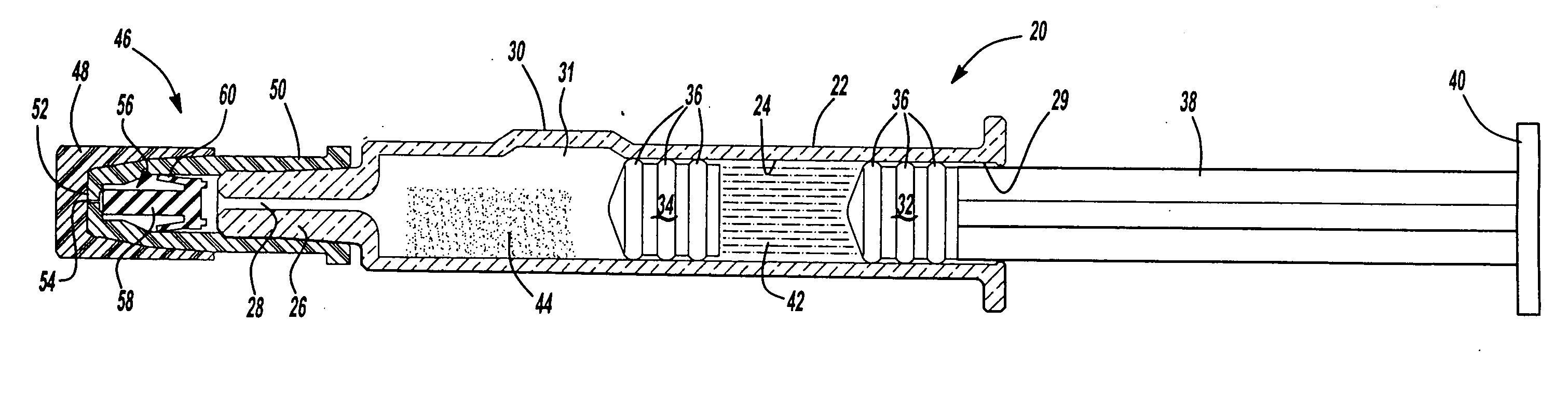
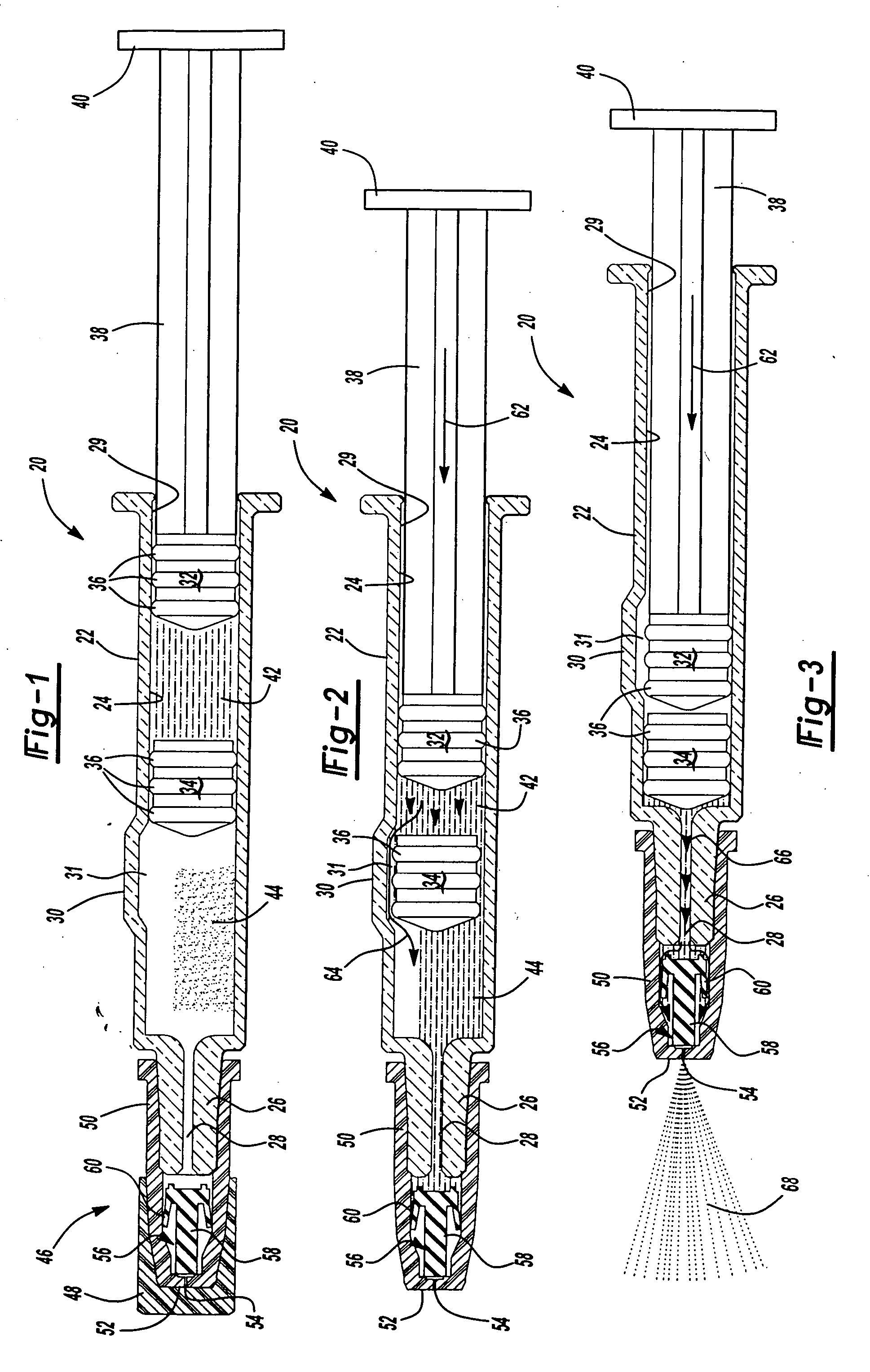
[0032] As set forth above, the spray device of this invention combines the advantages of a dual chamber or two-component syringe in a spray device for various spray applications of a medical substance, which eliminates the requirement of mixing the constituents of the substances using a hypodermic syringe or cartridge having a sharp needle cannula and a vial having an elastomeric stopper and malleable metal cap. The embodiments of the spray device of this invention illustrated in the drawings and described below provides mixing of substances in the body of the spray device and spray of a fine mist of medical substances for various applications including, but not limited to, the respiratory system of the patient through the nose or mouth, topical applications and other applications including, for example, applications through the patient's ear canal.

[0033] In the embodiment shown in FIGS. 1 to 3, the spray device 20 includes a tubular body or barrel 22 having a generally cylindrical...


PUM


Abstract

A spray device including a barrel having a bypass and at least two spaced stoppers defining a first and second chambers and a spray nozzle. Movement of the first stopper drives the second stopper to the bypass and the fluid in the first chamber into the second chamber, mixing the fluid and substance. Continued movement of the first and second stoppers drives the mixture through the spray nozzle. The spray device may include a third stopper having a body in the tubular barrel which is moved toward the spray nozzle. The movement of the third stopper provides space for the mixture and prevents unpressurized fluid from flowing through the spray nozzle. The third stopper includes an axial stalk. The stalk may be deformable or the stalk may be separate from the body and the spray nozzle includes a longitudinal internal passage which provides communication with the spray port.

Description

FIELD OF THE INVENTION [0001] This invention relates to a spray device which may be utilized to deliver an spray of medicament, drug, vaccine or other substances to a patient for various applications including but not limited to the respiratory system including the mouth or ear of a patient or for topical applications. More specifically, the spray device and method of application of this invention may be utilized to mix a fluid medicament, diluent or solvent or other substance in liquid, powder or lyophilized form and spray the mixture for application to a patient as described. BACKGROUND OF THE INVENTION [0002] Various spray devices have been developed by the applicant and others which have been in use for many years. As used herein, the terms “substance” or “medical substance” are intended to broadly cover any vaccine, drug, medicament or other substance which, when applied to a patient, results in the cure, alleviation, suspension, prevention, diagnosis or treatment of a disease ...

Claims


Application Information

Patent Timeline
Patent Type & Authority Applications(United States)
IPC IPC(8): A62C11/00A61J3/00A61M11/00A61M11/06A61M13/00A61M15/00B05B11/00B05B11/02
CPCA61M11/06A61M15/0028B05B11/0083B05B11/02A61M5/284A61M15/08A61M11/007
Inventor VEDRINE, LIONELBARRELLE, LAURENT
Owner BECTON DICKINSON & CO
Why Eureka
Try Eureka