Phosphor and plasma display panel using the same

a technology of phosphor and plasma display panel, which is applied in the direction of discharge tube luminescnet screen, gas-filled discharge tube, address electrode, etc., can solve the problems of p1 phosphor, difficult to positively charge the whole surface, and decrease in luminance, so as to improve after-glow characteristics, discharge properties, and good gray scale

Inactive Publication Date: 2006-07-13
SAMSUNG SDI CO LTD
View PDF7 Cites 24 Cited by
  • Summary
  • Abstract
  • Description
  • Claims
  • Application Information

AI Technical Summary

Benefits of technology

[0012] The present invention provides a phosphor that has a good gray scale, discharge properties, contra...

Problems solved by technology

However, when various phosphors are mixed, the good characteristics are present and the adverse effects also occur, and thus the selection of phosphors is very important.
However, in this case, the luminance decreases and it is difficult to positively charge the whole surface.
The P1 phosphor is disadvantageous in that the luminance is more rapidly saturated as the amount of Xe increases.
However, (Ba,Sr) MgAl4O23:Mn has a relatively long after-glow and a poor life span with respect to...

Method used


Image

  • Phosphor and plasma display panel using the same
  • Phosphor and plasma display panel using the same
  • Phosphor and plasma display panel using the same

Examples


example 1

[0066] Phosphor compositions were prepared as indicated in Table 1 and coated on to light emitting cells of a PDP to form a green phosphor layer. A discharge gas in the PDP included 55 wt % of Ne, 35 wt % of He, and 15 wt % of Xe.

[0067] In Example 1, the relative luminance, the CIE coordinate, and the decay time were investigated and are shown in Table 1.

[0068] The decay time was measured using an oscilloscope by measuring the time for the luminance of light emitted from the phosphor compositions due to excitation light of a pulsed Xe lamp was reduced to 1 / 10 of its initial luminance. The relative luminance was measured by injecting a mixed gas of 55 wt % Ne, 35 wt % He, and 15 wt % Xe in a discharge chamber and discharging the mixed gas. The relative luminance was determined using a commercially available P1 phosphor as a reference.

TABLE 1RelativeluminanceCIEComposition (wt %)(%)coordinateMgAl2O4:MnYBO3:TbY3Al5O12:Ce(Ex 147 nm)xyDecay time (ms)Zn2SiO4:Mn1000.2510.7017100950.178...

example 2

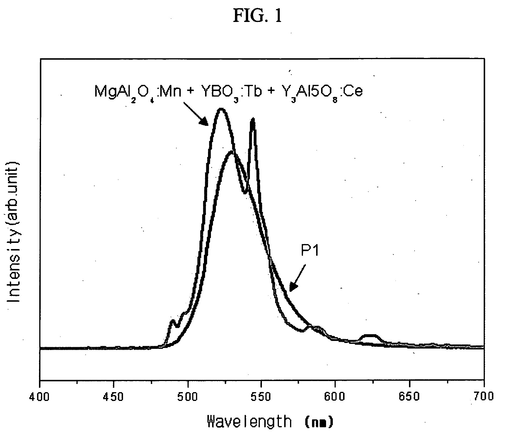
[0071] A phosphor composition of (Y,Gd)BO3:Eu as a red phosphor, BaMgAl10O19:Eu as a blue phosphor, and a mixture of 70 wt % MgAl2O4:Mn, 20 wt % (Y,Gd)BO3:Tb and 10 wt % Y3Al5O8:Ce as a green phosphor was prepared. The red, blue, green and white phosphor compositions were coated on light emitting cells to form white, red, blue, and green phosphor layers, respectively, to form a PDP. A discharge gas in the PDP included 55 wt % Ne, 35 wt % He and 15 wt % Xe.

[0072] In Example 2, the relative luminance, the CIE coordinate, and the decay time were measured and are shown in Table 2.

TABLE 2WhiteCIE x0.287CIE y0.308Luminance277Color temperature (K)9590RedCIE x0.644CIE y0.345Luminance135GreenCIE x0.217CIE y0.717Luminance327BlueCIE x0.153CIE y0.063Luminance42.9

[0073] It can be seen from Table 2 that the color reproduction range is significantly larger and a higher color temperature is obtained than when a conventional green phosphor is used.

example 3

[0074] Phosphor compositions with the composition and components shown in Table 3 were prepared and coated on red light emitting cells of a PDP to form phosphor layers. A discharge gas in the PDP included 55 wt % Ne, 35 wt % He and 15 wt % Xe.

[0075] In Example 3, the relative luminance, the CIE coordinate, and the decay time were investigated and are shown in Table 3.

TABLE 3DecayLumi-timeSampleCIE xCIE ynance(ms)(Y,Gd)BO3:Eu0.6490.350329Y2O3:Eu0.6550.34215490 parts by weight of (Y,Gd)BO3:Eu +0.6340.364320.910 parts by weight of YAG:Ce80 parts by weight of (Y,Gd)BO3:Eu +0.6290.378350.720 parts by weight of YAG:Ce70 parts by weight of (Y,Gd)BO3:Eu +0.6140.392380.530 parts by weight of YAG:Ce90 parts by weight of Y2O3:Eu +0.6410.356160.910 parts by weight of YAG:Ce80 parts by weight of Y2O3:Eu +0.6270.368170.720 parts by weight of YAG:Ce70 parts by weight of Y2O3:Eu +0.6130.38180.630 parts by weight of YAG:Ce

[0076] Table 3 shows that when a conventional red phosphor YAG:Ce is mixed ...


PUM


Abstract

A phosphor for a plasma display panel (PDP) has a decay time of about 1 ms or less when a Xe concentration is about 10 wt % to about 30 wt % based on the total weight of a discharge gas. A phosphor composition includes the same and a PDP includes a phosphor layer comprising the phosphor or the phosphor composition. When the phosphor or the phosphor composition are used, a low gray scale and low discharge problem due to a green phosphor of a PDP may be solved, a permanent afterimage due to a green phosphor is reduced, and a color reproduction range is significantly broadened compared to a conventional green phosphor of a PDP. In addition, the circuit of the PDP is simplified since colors are not individually subjected to gamma correction but are corrected using a single white gamma. Furthermore, the contrast in a light room is also improved due to the use of phosphor powders with color.

Description

CROSS REFERENCE TO RELATED APPLICATION [0001] This application claims priority to and the benefit of Korean Patent Application No. 10-2005-0002909, filed on Jan. 12, 2005, in the Korean Intellectual Property Office, the disclosure of which is incorporated herein in its entirety by reference. BACKGROUND OF THE INVENTION [0002] 1. Field of the Invention [0003] The present invention relates to a phosphor and a plasma display panel using the same, and more particularly, to a phosphor that has improved decay properties and a plasma display panel that has a phosphor layer formed using the same. [0004] 2. Description of the Background [0005] A plasma display panel (PDP) uses the emission of light resulting from a phosphor that is bombarded with ultra violet rays that are generated by the discharge of a mixed gas of Ne and Xe that is injected between glass substrates. In the PDP, the phosphor generates visible rays after receiving the resonance radiation (vacuum ultra violet rays of 147 nm)...

Claims


Application Information

Patent Timeline
IPC IPC(8): H01J1/62C09K11/08C09K11/64C09K11/78C09K11/80H01J11/12H01J11/22H01J11/24H01J11/26H01J11/34H01J11/36H01J11/38H01J11/40H01J11/42H01J11/50
CPCC09K11/595C09K11/643C09K11/7774C09K11/778C09K11/7787C09K11/7797E04H6/185G08G1/14
Inventor CHOI, ICK-KYUYOU, YOUNG-CHUIBAE, JAE-WOOKWON, SEON-YOUNGKIM, YONG-SEONSONG, MI-RANPARK, KYU-CHANLEE, HYUN-DEOKKIM, JI-HYUN
Owner SAMSUNG SDI CO LTD
Why Eureka
Try Eureka