
Battery pack capacity control system

Active Publication Date: 2006-07-13
TOYOTA JIDOSHA KK
View PDF4 Cites 38 Cited by
  • Summary
  • Abstract
  • Description
  • Claims
  • Application Information

AI Technical Summary

Benefits of technology

[0013] The invention has been accomplished in view of the aforementioned problems and the like, and provides battery control apparatus, method and program and a battery control system for a battery pack which are capable of controlling the charge / discharge of the battery pack with improved accuracy despite capacity differences (capacity variation).
[0015] According to the above-described battery pack charge / discharge control apparatus, an apparent state-of-charge value that is different from the control state-of-charge value is introduced. By computing an apparent state-of-charge value in accordance with the capacity difference value, it becomes possible to prevent, for example, an inconvenience in which it is determined that the control state-of-charge value cannot be increased to a control center value due to a capacity difference value.
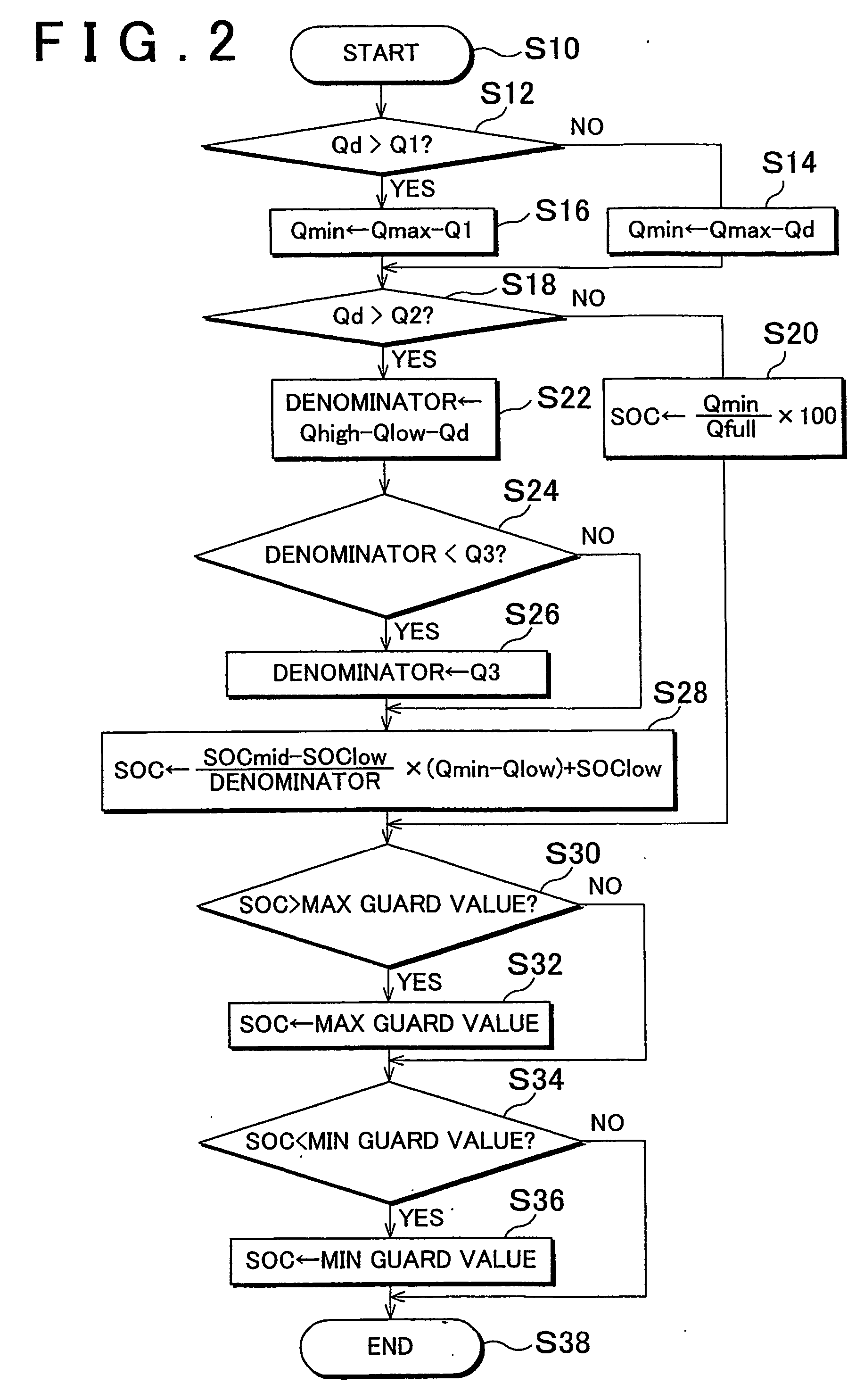
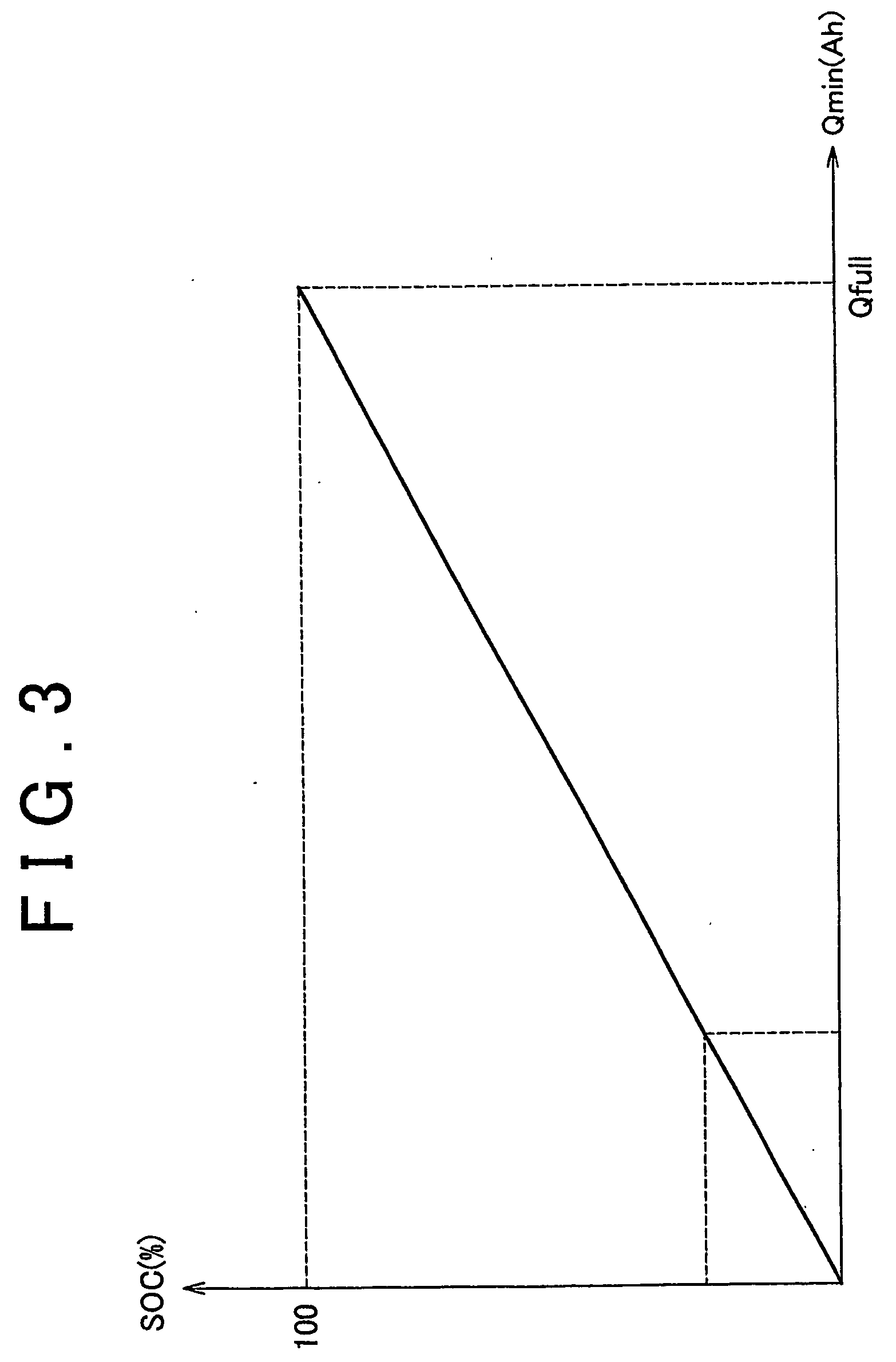
[0019] If the capacity difference value is less than the predetermined capacity difference, a control apparatus employing a control method proposed in Japanese Patent Application No. 2002-43216 is introduced. That is, the minimum capacity value among the unit batteries that constitute the battery pack is computed, and the minimum capacity value is used as a control state-of-charge value to perform the control. Therefore, advantages of this prior application can be exploited, so that charge / discharge control with improved precision will become possible.
[0022] This prevents the capacity difference value from becoming excessively great, thereby preventing occurrence of a deficiency in the computation that uses the capacity difference.
[0031] The invention provides battery control apparatus, method and program and a battery control system for a battery pack which are capable of controlling the charge / discharge of the battery pack with improved precision.

Problems solved by technology

The method disclosed in Japanese Patent Application Laid-Open Publication No. 2000-14029 has a problem of complicated computation for the SOC control since the SOC is controlled with reference to the lower and upper limit values of the control range.
However, according to the control method of the aforementioned patent application, it sometimes becomes impossible to increase the representative SOC to a control center value if the capacity variation among the unit batteries (capacity differences among the unit batteries) becomes great (e.g., if the capacity variation rapidly increases due to occurrence of an abnormality or the like within the battery in addition to an increase in the capacity variation resulting from the normal use of the battery).
If the representative SOC cannot be increased to the control center value, there occurs an inconvenience in which even though the battery pack is actually charged to a considerable extent, it is determined that recovery to a sufficiently charged state has not been accomplished.
If this event happens, the charging of the battery pack does not stop but inconveniently continues.
Furthermore, during a run of the vehicle, as it is determined that charging is incomplete despite accomplishment of practically maximum charge, the engine power is consumed for the charging of the battery pack 112 by the generator in addition to the driving of the vehicle by the vehicle-driving motor.
Hence, there occurs a case where during a run of the vehicle that requires increased power, for example, an uphill run or the like, sufficient energy cannot be supplied for the driving of the vehicle, thus failing to meet a drivability requirement.

Method used


Image

  • Battery pack capacity control system
  • Battery pack capacity control system
  • Battery pack capacity control system

Examples


Embodiment Construction

[0041] In the following description and the accompanying drawings, the present invention will be described in more detail in terms of exemplary embodiments.

[0042] [Construction in Which Invention is Applied to Hybrid Electric Vehicle (Battery Control System)]

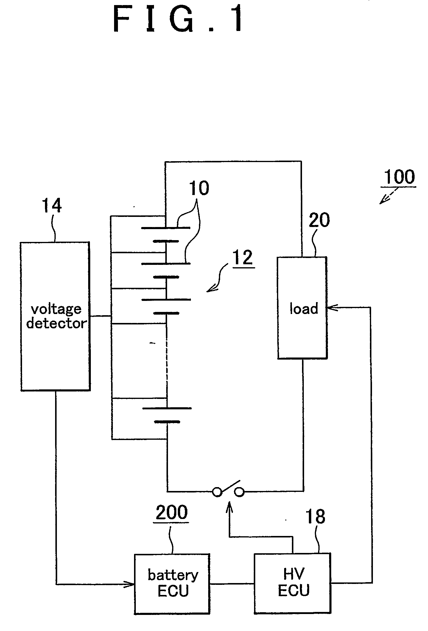
[0043]FIG. 1 illustrates a battery control system 100 where a charge / discharge control program in accordance with the invention is applied to a hybrid electric vehicle. The charge / discharge control program of the invention is installed in a battery ECU 200 that is a computer. A battery pack 12 includes a plurality of unit batteries (battery cells or battery blocks) 10 that are connected in series. A voltage detector 14 for detecting the voltage of each unit battery 10 is connected to the battery pack 12. On the basis of the output of the voltage detector 14, the battery ECU 200 computes the SOC of each one of the battery blocks 10 that constitute the battery pack 12. The battery ECU 200 computes the SOC to be transmitted to an ...


PUM


Abstract

If the capacity variation is greater than a pre-stored value, the SOC converted from Qmin sometimes cannot recover to a control center value. In such a case, inconveniences including the continuation of an event where the HVECU cannot output a command to stop the charging are prevented by computing an apparatus SOC and reporting the SOC to the HVECU. The apparent SOC is computed by increasing the value of SOC in accordance with the magnitude of the capacity variation. The thus-computed apparent SOC is reported to the HVECU by the battery ECU, so that it can be determined that the control center value has been exceeded. Thus, it becomes possible to provide battery control apparatus, method and program and a battery control system for a battery pack which are capable of controlling the charging / discharging of the battery pack with an improved accuracy despite capacity variation.

Description

[0001] This is a 371 national phase application of PCT / IB2004 / 002385 filed 26 Jul. 2004, claiming priority to Japanese Patent Application No. 2003-281429 filed 29 Jul. 2003, the contents of which are incorporated herein by reference.BACKGROUND OF THE INVENTION [0002] 1. Field of the Invention [0003] The invention relates to charge / discharge control apparatus, method and program for controlling the charging and discharging of a secondary battery formed by a battery pack constituted of a plurality of unit batteries, and a battery control system. [0004] 2. Description of the Related Art [0005] Hybrid vehicles equipped with an electric power generator driven by an engine, in addition to a vehicle-driving electric motor, are known. In such a hybrid vehicle, a battery pack formed by connecting a plurality of unit batteries (e.g., battery cells, battery blocks, etc.) in series is mounted. The battery pack drives the vehicle-driving motor by supplying electric power to the motor, and is cha...

Claims


Application Information

Patent Timeline
IPC IPC(8): H02J7/00H02J7/02G01R31/36H01M10/44H02J7/34
CPCG01R31/3651H02J7/0021H02J7/0031Y02T10/7055G01R31/367Y02T10/70H02J7/0048H02J7/0014
Inventor ISHISHITA, TERUO
Owner TOYOTA JIDOSHA KK
Learn More