
Demodulation

a demodulation and filter technology, applied in the field of demodulation, can solve the problems of delayed and filtered versions of soi, and achieve the effect of improving the ability of adaptive transversal filtering and improving the ability of filtering

Inactive Publication Date: 2006-07-13
BOSE CORP
View PDF14 Cites 66 Cited by
  • Summary
  • Abstract
  • Description
  • Claims
  • Application Information

AI Technical Summary

Benefits of technology

[0018] The present invention analyzes the received signal to determine if an overlapping, adjacent interfering signal is present. If an interfering signal is detected, the initialization of the adaptive filter is altered in a manner that significantly improves the ability of the filter to converge to the solution that selects the desired signal and rejects the interfering signal. The process that alters the initialization is called altering the mode of the adaptive filter. The present invention comprises a mode controlled blind adaptive transversal filter. The invention substantially improves the ability of an adaptive transversal filter to converge to a desired solution when operating under nonideal conditions (i.e. conditions that give rise to a solution space with more than one minimum).

Problems solved by technology

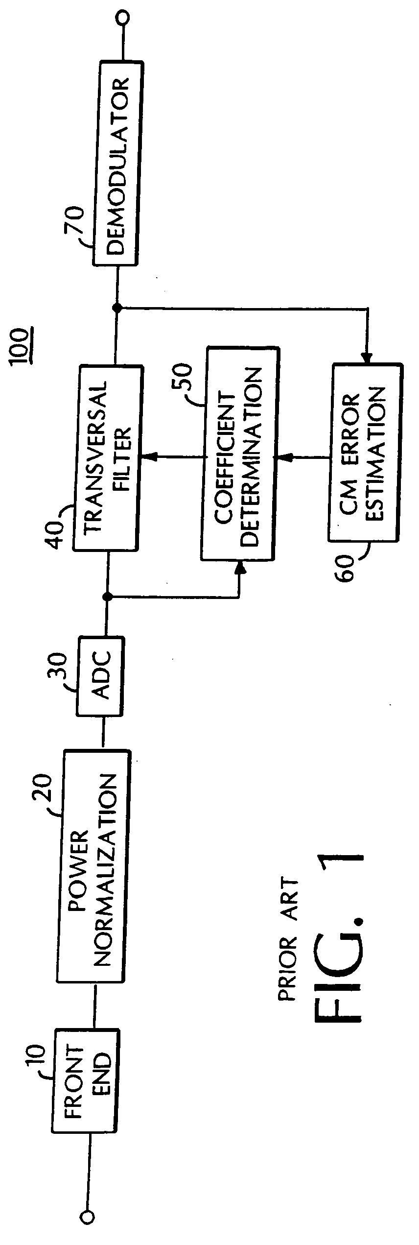
The delayed and filtered versions of the SOI result from reflections and other irregularities.

Method used


Image

  • Demodulation
  • Demodulation
  • Demodulation

Examples


Embodiment Construction

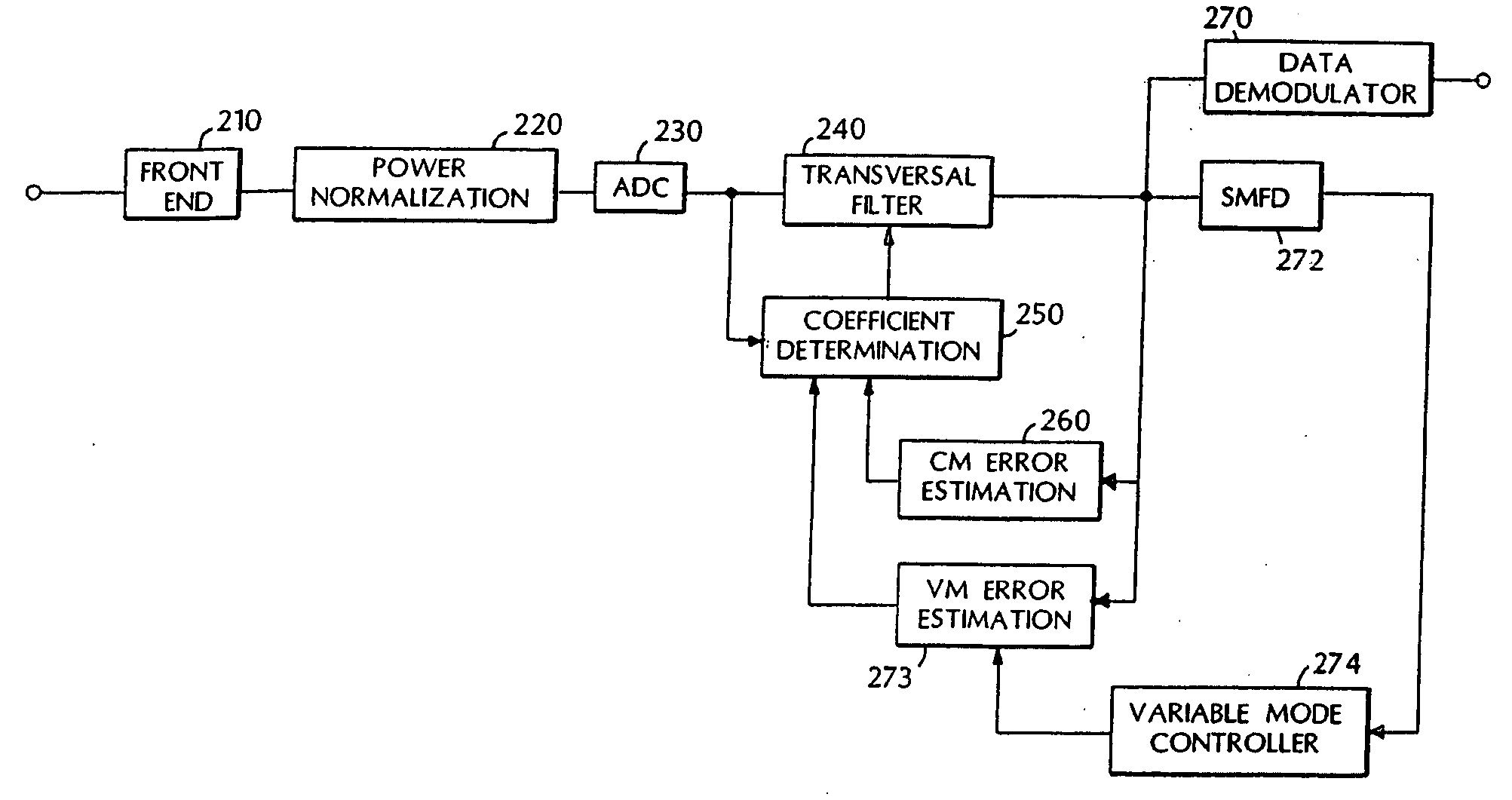
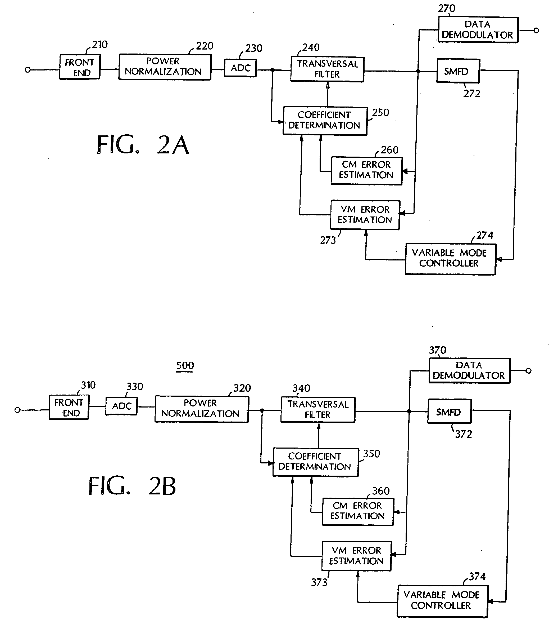
[0030] Eq. 1 in combination with Eqs. 5-8 provide the mathematical foundation for the Mode Controlled Blind Adaptive Transversal Filter of the present invention. FIG. 2a is a block diagram of an embodiment of the invention. FIG. 2b is a block diagram of an alternative embodiment of the invention.

[0031] The coefficients characterizing the transversal filter are stored in a vector W. For a filter characterized by N coefficients, the vector W will have N elements. The updates of L arbitrary coefficient vector elements, where N>L≧1, is determined in accordance with Eqs. 2-4 (i.e. one or more coefficients are updated in accordance with the constant modulus error estimate ecm). The remaining N-L coefficient elements are updated in accordance with equations 6 and 7 below. The subscript g refers to the L coefficients updated in accordance with Eqs. 2-4, and h to refer to the N-L other coefficients updated using the variable mode error estimate evm in accordance with Eq. 7. The L coefficien...


PUM


Abstract

Demodulation apparatus includes a transversal filter characterized by coefficients adjusted by a coefficient determiner responsive to a constant modulus error signal and variable mode error signal related to the output of a spectral mean frequency detector having its input coupled to the output of the transversal filter.

Description

[0001] The present invention relates in general to recovering data from modulated signals. More particularly, the present invention concerns reducing the effects of multipath and adjacent channel interference, and other linear time invariant (or slowly time varying) operations that may be applied intentionally or unintentionally to a modulated signal. The invention finds particular use as an adaptive transmission channel equalizer, where it operates to reduce anomalies in a received signal that result from nonidealities in a transmission channel. The invention comprises an adaptive filter structure configured to act as an adaptive equalizer that uses a novel method of adaptation, wherein the error cost function used to adjust the coefficients of the adaptive filter is itself adjusted, based on characteristics of the received signal. [0002] The invention has utility in any system where it is desired to recover data from a modulated signal, where the modulated signal has the following...

Claims


Application Information

Patent Timeline
Patent Type & Authority Applications(United States)
IPC IPC(8): H03D3/00H04B7/005H04B3/06H04L25/03
CPCH04L25/03006H04L25/0305H04L2025/0363H04L2025/03726
Inventor BARKSDALE, TOBE
Owner BOSE CORP
Learn More