Control device and control method capable of external synchronization

a control device and control method technology, applied in the direction of electric programme control, instruments, horology, etc., can solve the problems of troublesome replacement operation in the event of failure, change in the processing cycle of control interrupt processing, and general deterioration of control accuracy, so as to maintain the control processing cycle constant and increase the maximum process time

Inactive Publication Date: 2006-07-13
YASKAWA DENKI KK
View PDF3 Cites 5 Cited by
  • Summary
  • Abstract
  • Description
  • Claims
  • Application Information

AI Technical Summary

Benefits of technology

[0044] According to the control methods of Present Inventions 5 to 7, the performance of the CPU can be fully exhibited by increasing the maximum process time allowed for control processing. By means of adjustment of the process time, even when changes occur in de

Problems solved by technology

Hence, the control processing cycle at which the control interrupt processing is performed changes, and control accuracy is generally deteriorated.
Replacement operation required in the event of occurrence of a failure is troublesome.
When the host controller is combined with a controller whose clock signal used for generating a synchronizing signal of the host controller is slower than the clock signal used for

Method used


Image

  • Control device and control method capable of external synchronization
  • Control device and control method capable of external synchronization
  • Control device and control method capable of external synchronization

Examples


first embodiment

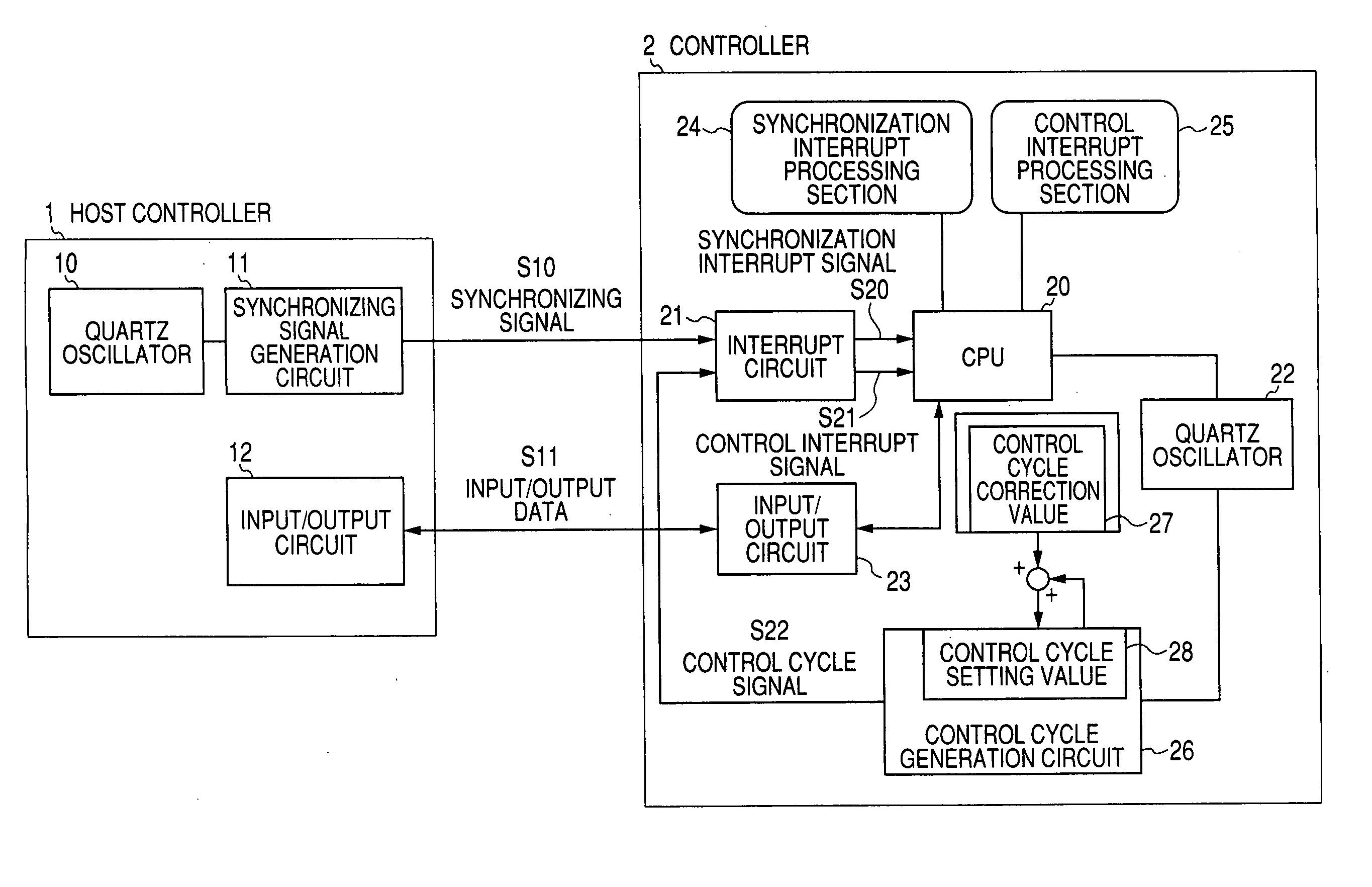
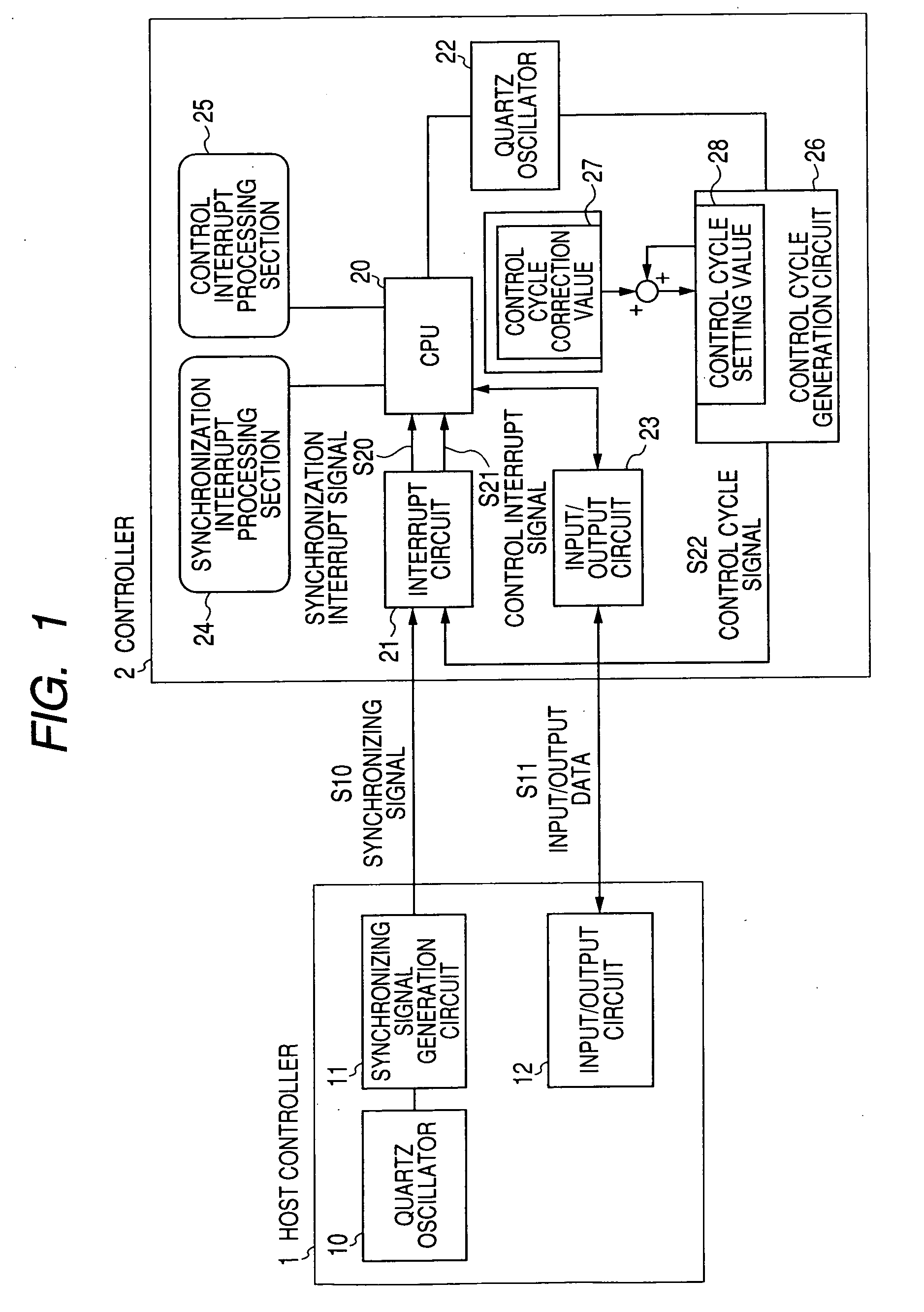
[0056]FIG. 1 is a block diagram showing the configuration of a controller according to the present invention.

[0057] In FIG. 1, reference numeral 1 designates a host controller having the function of outputting a synchronizing signal to the outside, the function of outputting data to the outside, and the function of receiving an input of data from the outside. Reference numeral 10 designates a quartz oscillator which generates a clock signal. Reference numeral 11 designates a synchronizing signal generation circuit, which generates a signal during a predetermined cycle on the basis of a clock signal output from the quartz oscillator 10 and outputs the thus-generated signal to the outside. Reference numeral 12 designates an input / output circuit, which outputs data to the controller and receives an input of data from the controller. S10 designates a synchronizing signal, which is generated during a given cycle by the synchronizing signal generation circuit 11. Reference numeral S11 des...

second embodiment

[0065] the present invention will now be described by reference to FIG. 3.

[0066] A block diagram showing the configuration of the second embodiment is identical with that shown in FIG. 1. Moreover, a view showing operation of software is identical with that shown in FIG. 2. A difference between the first and second embodiments lies in a time required to adjust the control cycle generation circuit.

[0067]FIG. 3 is a timing chart showing operation of the controller according to the second embodiment of the present invention.

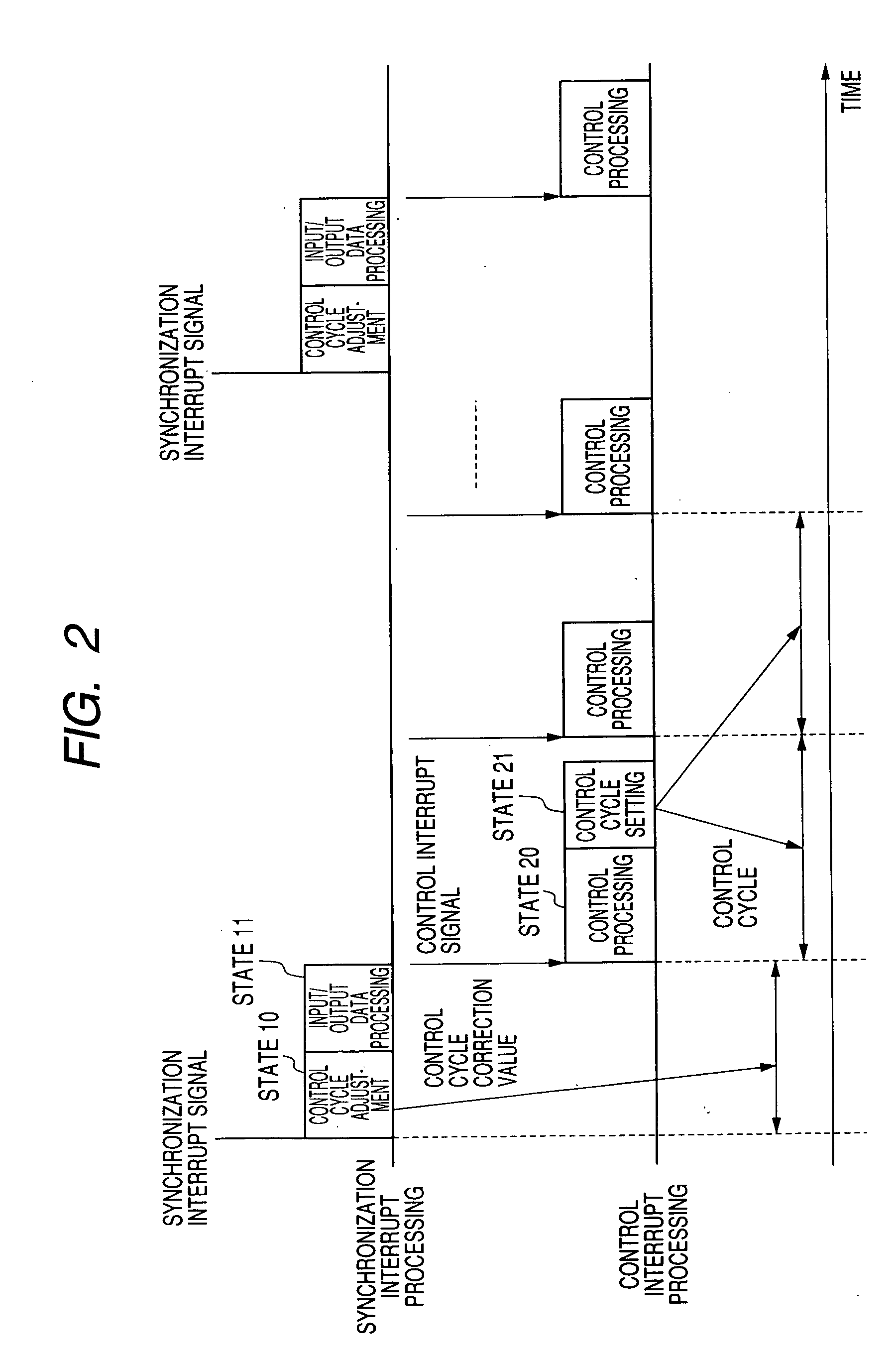
[0068] In FIG. 3, when the synchronizing signal S10 generated during a predetermined cycle by the host controller 1 (shown in FIG. 1) is input, the interrupt circuit 21 generates the synchronization interrupt signal S20, and the CPU 20 activates the synchronization interrupt processing section 24, whereby synchronization interrupt processing is performed. In general, when synchronization interrupt processing does not involve conditional judgment, the time required...

third embodiment

[0074]FIG. 4 is a block diagram showing the configuration of a controller according to the present invention.

[0075] In FIG. 4, reference numeral 100 designates a host controller having the function of outputting a synchronizing signal to the outside, the function of outputting data to the outside, and the function of receiving an input of data from the outside.

[0076] Reference numeral 110 designates a quartz oscillator which generates a clock signal. Reference numeral 111 designates a synchronizing signal generation circuit, which generates a signal during a predetermined cycle on the basis of a clock signal output from the quartz oscillator 110 and outputs the thus-generated signal to the outside. Reference numeral 112 designates an input / output circuit, which outputs data to the controller and receives an input of data from the controller. S110 designates a synchronizing signal, which is generated during a given cycle by the synchronizing signal generation circuit 111. Reference ...


PUM


Abstract

The problem to be met by the present invention is to provide a controller which can execute control processing in synchronism with a synchronizing signal output from a host controller without taking into consideration a difference between a clock signal used for generating a synchronizing signal of the host controller and a clock signal used for generating a control cycle signal of a controller; and can enhance accuracy performance of control. According to the present invention, in a controller having a control interrupt processing section, a synchronization interrupt processing section adjusts means for generating a control cycle signal to thus generate a control interrupt signal such that the control cycle signal is generated while being delayed by an amount equal to or greater than the duration of an accuracy error between a quartz oscillator used for generating a synchronization interrupt signal and a quartz oscillator used for generating the control cycle signal, thereby executing control interrupt processing in synchronism with the synchronizing signal from the outside.

Description

FIELD OF THE INVENTION [0001] The present invention relates to a controller having the function of performing control processing in synchronism with a synchronizing signal input from the outside such as a high-level controller, as well as to a method for controlling the controller BACKGROUND TECHNIQUE [0002] A conventional controller will be described by reference to the drawings. [0003]FIG. 8 is a block diagram showing the configuration of a conventional controller, and FIG. 9 is a timing chart for describing operation of the controller. [0004] In FIG. 8, reference numeral 1 designates a host controller, and the apparatus has the function of outputting a synchronizing signal to the outside, the function of outputting data to the outside, and the function of receiving an input of data from the outside. Reference numeral 10 designates a quartz oscillator, which generates a clock signal. Reference numeral 11 designates a synchronizing signal generation circuit, which periodically gene...

Claims


Application Information

Patent Timeline
IPC IPC(8): G04C11/02G05B19/05
CPCG05B19/05
Inventor MIYAMATSU, TOSHIYUKIKUZUSHIMA, MITSUNORI
Owner YASKAWA DENKI KK
Why Eureka
Try Eureka