Microphone and sound amplification system

a technology of sound amplification and microphone, applied in the field of microphones, can solve the problems of increasing cost, difficult to effectively cancel the disclosed howling canceller, and difficult to incorporate the howling canceller into an existing amplifier device, and achieve the effect of reliable cancellation of howling

Inactive Publication Date: 2006-07-13
YAMAHA CORP
View PDF2 Cites 80 Cited by
  • Summary
  • Abstract
  • Description
  • Claims
  • Application Information

AI Technical Summary

Benefits of technology

[0013] In view of the foregoing, it is an object of the present invention to provide an improved microphone and sound amplification system which can reliably cancel howling even where the microphone is connected to an existing amplifier device or where a plurality of the microphones are connected to a single amplifier device.

Problems solved by technology

Thus, although the howling canceller can be incorporated into an amplifier device in advance, it is extremely difficult to incorporate the howling canceller into an existing amplifier device.
Therefore, in order to effectively cancel howling, it is necessary to purchase another amplifier device with the howling canceler incorporated therein, which would therefore result in increased cost.
Therefore, the disclosed howling canceler can not separately deal with individual feedback signals to be re-input to the plurality of microphones, so that it is difficult for the disclosed howling canceler to effectively cancel howling.

Method used


Image

  • Microphone and sound amplification system
  • Microphone and sound amplification system
  • Microphone and sound amplification system

Examples


first embodiment

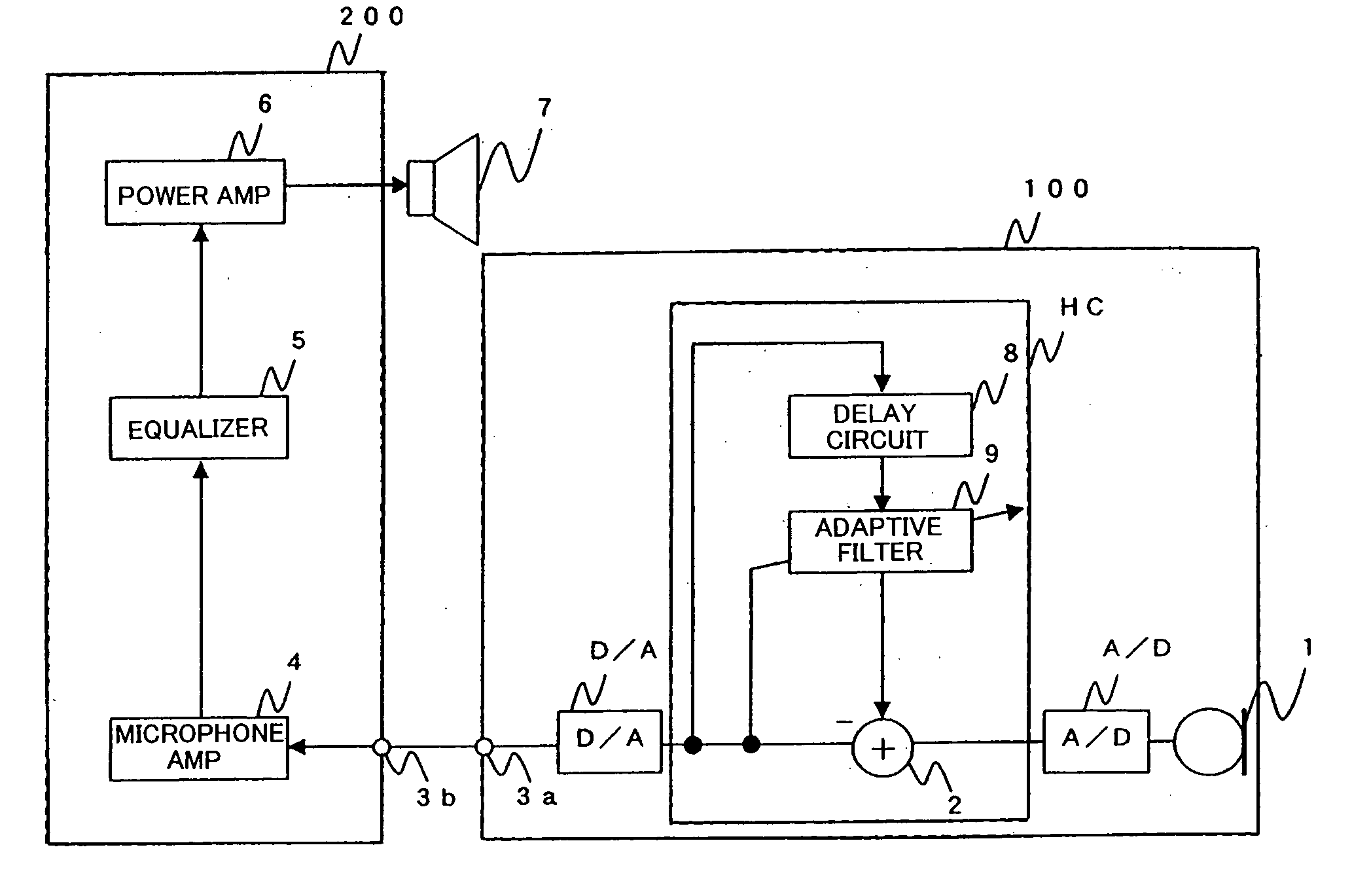
[0044]FIG. 1 is a block diagram of a sound amplification apparatus in accordance with a first embodiment of the present invention. As shown, the sound amplification apparatus comprises: a microphone 100 including a sound-collecting microphone element 1, A / D converter, howling canceller HC, D / A converter and connecting terminal 3a; an amplifier device 200 including a connecting terminal 3b, microphone amplifier 4, equalizer 5 and power amplifier 6; and a speaker 7. Note that a microphone amplifier may be provided between the microphone element 1 and the A / D converter, in which case the amplifier device 200 need not include the microphone amplifier 4.

[0045] The howling canceller HC includes an adder 2 between the A / D converter and the D / A converter, an adaptive filter 9 for supplying a simulative feedback signal to the adder 2, and a delay circuit 8 for delaying a residual signal, output from the adder 2, by a predetermined time and supplying the thus-delayed residual signal to the a...

second embodiment

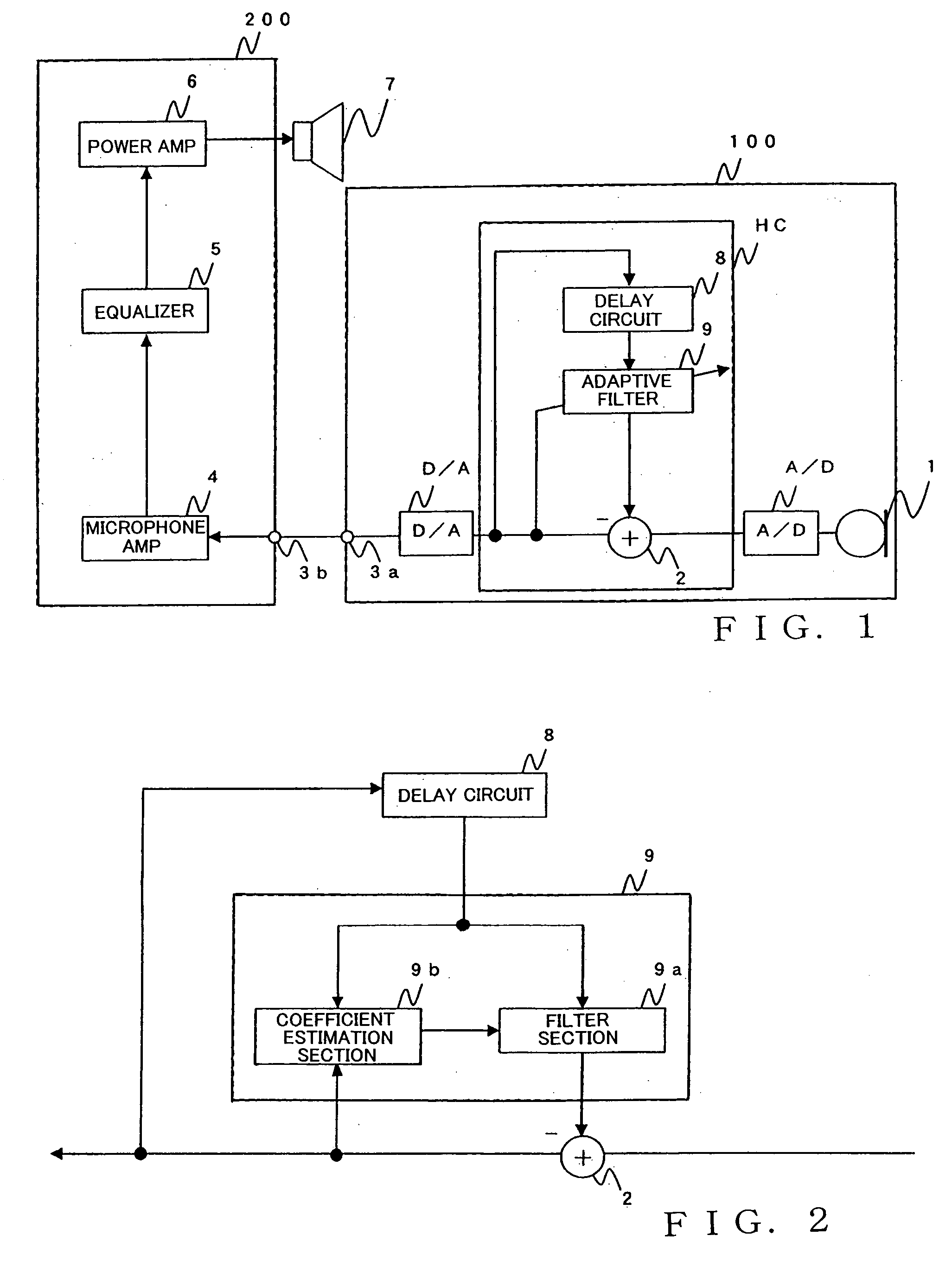
[0062]FIG. 4 is a block diagram of a sound amplification apparatus in accordance with a second embodiment of the present invention. In FIG. 4, the same components as in the first embodiment are indicated by the same reference characters and will not be described in detail here to avoid unnecessary duplication. The sound amplification apparatus according to the second embodiment includes, in place of the microphone 100 in the first embodiment, a microphone 101 where a reproduction section 10 is connected to the path between the adder 2 and the delay circuit 8.

[0063] The reproduction section 10 is implemented by a digital filter (simulating amplifier filter) that filters the output signal from the adder 2 and outputs the thus-filtered signal to the delay circuit 8. Transfer function of the reproduction section 10 is determined in advance assuming an ordinary sound amplification apparatus or the like. Thus, each signal input to the delay circuit 8 approximates a signal actually transf...

fourth embodiment

[0085]FIG. 10 is a block diagram of a sound amplification apparatus in accordance with a fourth embodiment of the present invention. In FIG. 10, the same components as in the first embodiment are indicated by the same reference characters and will not be described in detail here to avoid unnecessary duplication. As shown, the sound amplification apparatus according to the fourth embodiment includes a microphone 104 provided with a signal receiver section 21 connected to the delay circuit 8, and an amplifier unit 204 provided with a signal transmitter section 20 connected between the power amplifier 6 and the speaker 7.

[0086] The signal transmitter section 20 acquires each signal to be transferred to the speaker 7 and transmits the acquired signal to the signal receiver section 21 of the microphone 104. The signal to be transferred to the speaker 7 after having been received by the signal receiver section 21, is converted via the A / D converter into a digital signal, and the thus-con...


PUM


Abstract

Microphone includes: a microphone element; a simulative feedback signal generation section that generates a simulative feedback signal simulating a feedback signal generated by a sound, produced via a speaker, returning the microphone element; and an arithmetic operator that subtracts the simulative feedback signal, generated by the simulative feedback signal generation section, from a sound signal collected by the microphone element, to thereby output the subtraction result as a residual signal. The residual signal output by the arithmetic operator is supplied to an amplifier device of the speaker as an output signal of the microphone. The simulative feedback signal generation section includes a delay circuit that delays the residual signal, output by the arithmetic operator, by a given time, and an adaptive filter that generates the simulative feedback signal by filtering a previous residual signal delayed by the delay circuit. The adaptive filter updates a filter coefficient on the basis of the previous residual signal delayed by the delay circuit and a current residual signal output by the arithmetic operator.

Description

BACKGROUND OF THE INVENTION [0001] The present invention relates to microphones capable of preventing howling, and sound amplification systems suitable for installation in auditoriums, halls, etc. and capable of preventing howling. [0002] Generally, in cases where a sound amplification apparatus is installed in an auditorium, hall or the like, sounds output from a speaker are fed back to a microphone via a sound path having a given transfer function. Namely, a closed loop is formed by the microphone, amplifier, speaker, sound path and microphone. If the gain of the closed loop exceeds one, a sound returning from the speaker to the microphone would be enhanced to cause howling. To reliably prevent such howling, there have been proposed howling cancellers which prevent occurrence of howling using an adaptive digital filter (hereinafter “adaptive filter”) (see, for example, “Howling Canceller in Sound Amplification System Using LMS Algorithm”, by Inazumi, Imai and Konishi, in Proceedin...

Claims


Application Information

Patent Timeline
Patent Type & Authority Applications(United States)
IPC IPC(8): H04B3/20H04R3/00
CPCH04R3/02
Inventor FUJITA, HIROAKIOKUMURA, HIRAKU
Owner YAMAHA CORP
Why Eureka
Try Eureka