Manufacturing method and readout system for biopolymer arrays

a biopolymer array and readout system technology, applied in the direction of burettes/pipettes, sequential/parallax process reactions, library creation, etc., can solve the problems of inherently long and expensive methods, dna arrays (either on silicon, glass or plastic) can cost as much as $1200 each, and fluorescence analyzers are expensiv

Inactive Publication Date: 2006-07-13
NEW LIGHT IND
View PDF3 Cites 27 Cited by
  • Summary
  • Abstract
  • Description
  • Claims
  • Application Information

AI Technical Summary

Benefits of technology

[0022] Also disclosed is a system for producing chemical arrays on a roll-to-roll basis. This system has a plurality of exposure modules, each comprising a variable masking system, a light source and imaging optics to image a line of pixels from a variable mask to a line on a surface. A plurality of photochemical modules function to bring reactants of a photo controllable chemistry in contact with a substrate bearing reaction loci, such that at each photochemical module is associated with at least one exposure module such that the variable masking system of the exposure module controls illumination of a line of reaction loci on the substrate and thereby controls the photo-controllable chemistry in a spatial pattern of loci according to the variable masking system, such that the plurality of photochemical modules and their associated exposure modules effect an individually predetermined sequence of photo-controlled reactions at each locus on the substrate.

Problems solved by technology

The method is inherently lengthy and expensive, so that individual DNA arrays (either on silicon, glass or plastic) can cost as much as $1200 each.
The fluorescence analyzer is expensive and often misreads the locations of individual array elements.
However, such cantilever arrays would have some potential problems of clogging and would be even more expensive to manufacture than the passive arrays commonly used with fluorescence readout

Method used


Image

  • Manufacturing method and readout system for biopolymer arrays
  • Manufacturing method and readout system for biopolymer arrays
  • Manufacturing method and readout system for biopolymer arrays

Examples


Embodiment Construction

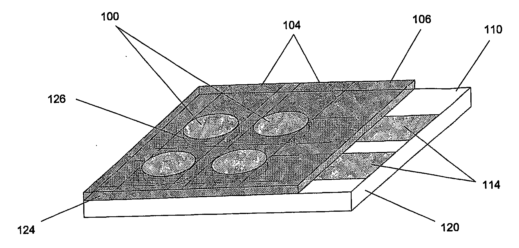
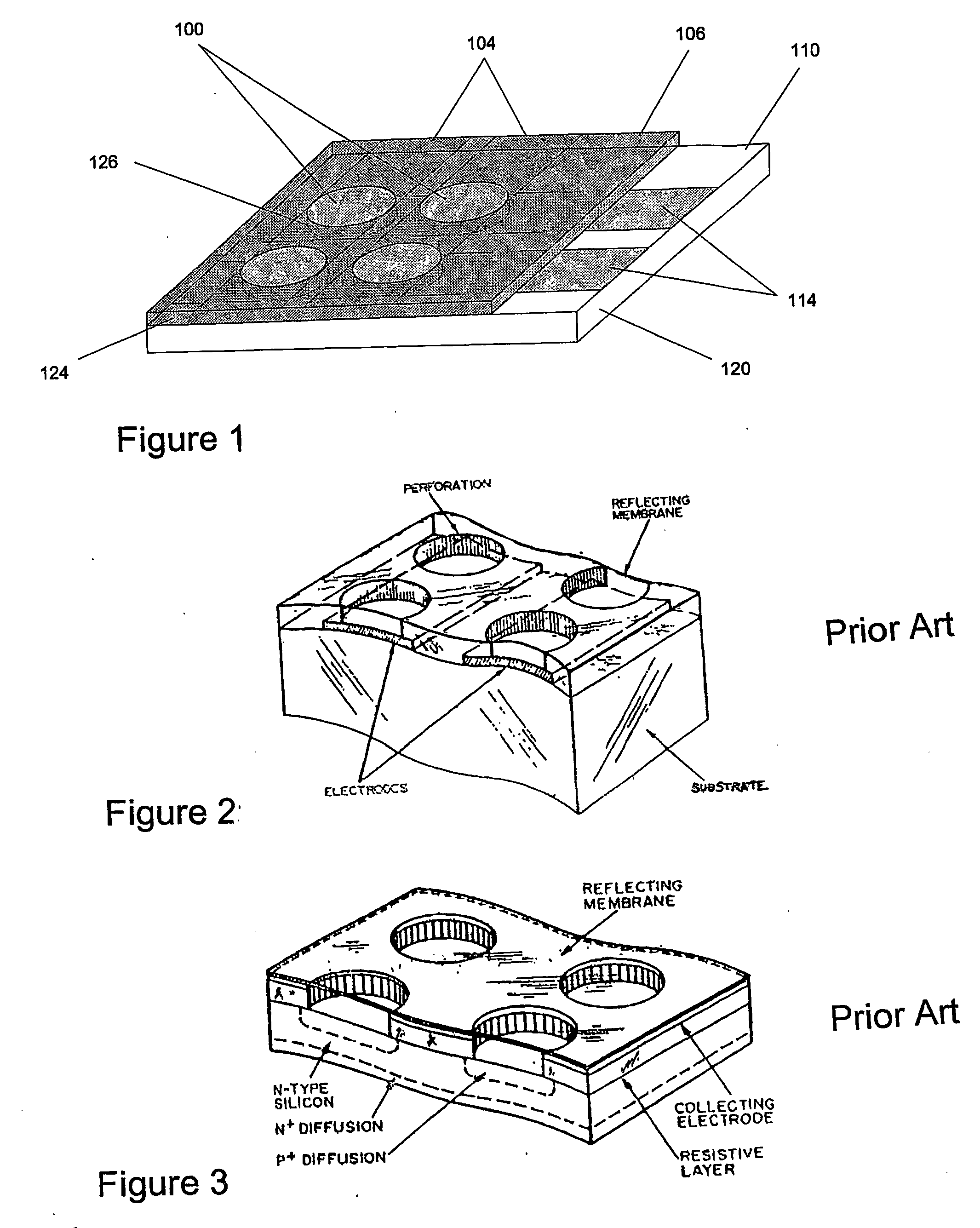
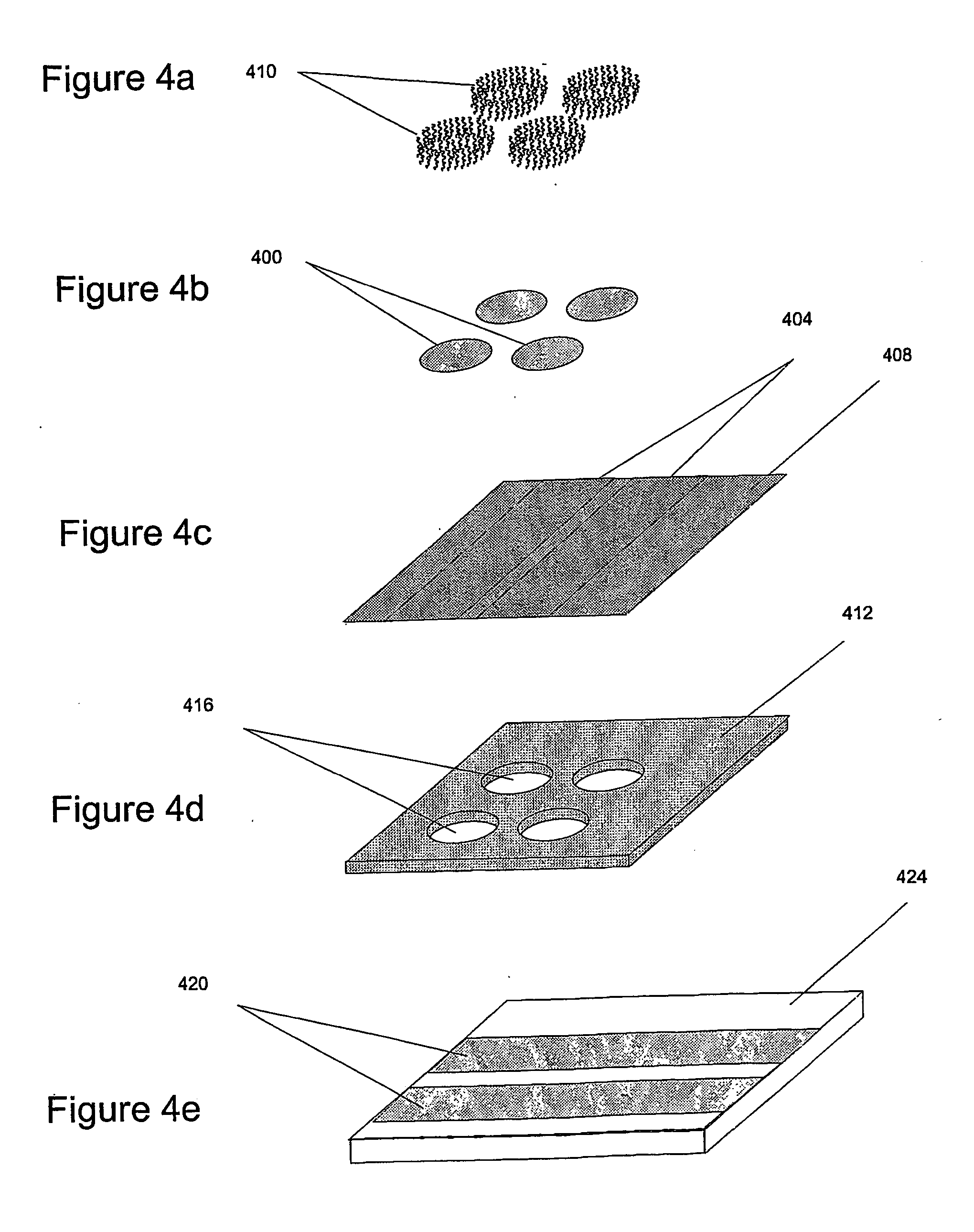
[0051] The present invention has two important aspects: First, providing a simple way (Hybridization Transfer Printing) to eliminate the many steps involved in building a DNA, antibody, antigen or microbe array; and a simple electrically-driven sensor array to detect the presence of complementary hybridization to 30 individual elements in the array. The invention uses essentially the same techniques to produce and analyze DNA arrays, microbe arrays, antibody arrays and antigen arrays. By greatly reducing the number of steps to manufacture arrays for specific hybridization and providing a simple and easily manufacturable sensor array, the present invention solves the problems of cost and complexity in DNA chip manufacture and opens a host of new practical applications for hybridization arrays. The second general aspect is a Tympanic Sensor Array that allows electronic detection of multiple binding events occurring on an array.

I. Hybridization Transfer Printing

[0052] The inventive ...


PUM

PropertyMeasurementUnit
resonant frequencyaaaaaaaaaa
thicknessaaaaaaaaaa
massaaaaaaaaaa

Abstract

A method for manufacturing an array of biomolecules that have complementary binding species is disclosed. The method utilize a master substrate containing a desired master array of binding molecules or ligands, e.g., DNA target molecules. A mixture of complementary, antiligand molecules, e.g., DNA probe molecules, are then hybridized to the ligands of the master array, Forming an array of antiligand molecules reversibly bound to the molecules in the master array. The antiligand array is then transferred and bound to a separate substrate, to form a desired array of antiligand molecules on the separate substrate. The process may be repeated to produce multiple arrays or multiple generations of arrays. Also disclosed is a sensor array device and method. The device includes an array of vibratory tympanic elements, each having a specific analyte binding probe carried on the vibratory membrane of the element. A binding event is detected by a change in the vibrational resonance of a selected element.

Description

SUMMARY OF THE INVENTION [0001] A method is described for manufacturing DNA arrays and the like, using a hybridization transfer printing process to replicate an original DNA array onto a new kind of sensor array. The hybridization transfer printing produces a reverse replica of an entire DNA array comprising any number of different DNA segments. The sensor array enables direct electrical readout to determine the presence of complementary DNA bound to the DNA array at each element of the sensor array. BACKGROUND OF THE INVENTION [0002] DNA arrays and antibody or antigen arrays have become common tools for DNA sequencing, DNA analysis, protein analysis, detection of specific microbial species, disease diagnosis, and other such purposes. See, for example, U.S. Pat. Nos. 6,376,191, 6,368,799, 6,316,197, 6,309,824, 6,309,823, 6,245,511, 6,232,068, 6,027,890, and 5,861,242, 5,856,101, all of which are incorporated herein by reference. The arrays are commonly either built up by an automate...

Claims


Application Information

Patent Timeline
Patent Type & Authority Applications(United States)
IPC IPC(8): C12Q1/68C12M1/34B01L3/02G01N27/00B01J19/00C12NC40B40/06C40B50/14G01N27/26
CPCB01J19/0046B01J2219/00385B01J2219/00432B01J2219/00434B01J2219/00439B01J2219/00497B01J2219/00518B01J2219/00527B01J2219/00538B01J2219/00585B01J2219/00596B01J2219/00605B01J2219/0061B01J2219/00612B01J2219/00621B01J2219/00626B01J2219/00637B01J2219/00653B01J2219/00657B01J2219/00659B01J2219/00675B01J2219/00677B01J2219/00704B01J2219/00711B01J2219/00722B01J2219/00725B01L3/5085B82Y30/00C12Q1/6825C12Q1/6837C40B40/06C40B50/14G01N33/54373C12Q2565/501C12Q2565/607C12Q2565/515
Inventor MCGREW, STEPHENLIGHTFOOT, DONALD
Owner NEW LIGHT IND
Why Eureka
Try Eureka