Bioreactors with substance injection capacity

a bioreactor and substance technology, applied in the field of living system growth and maintenance, can solve the problems of low productivity, affecting the growth of mammalian cells, and the liquid-gas interface created in some reactor models is particularly damaging to mammalian cells, and achieves the effect of reducing pressur

Inactive Publication Date: 2006-07-13
VANDERBILT UNIV
View PDF21 Cites 233 Cited by
  • Summary
  • Abstract
  • Description
  • Claims
  • Application Information

AI Technical Summary

Benefits of technology

[0035] The perfusion means further includes a perfusion supply network in fluid communication with the nanofilter through the pores. In one embodiment, the perfusion supply network includes a plurality of perfusion channels, each being in fluid communication with the nanofilter to allow bidirectional, diffusional exchange of nutrients and metabolic byproducts with the nanofilter and being dimensioned to minimize pressure drops along each perfusion channel and to allow passive diffusional exchange of nutrients and metabolic byproducts along each perfusion channel.
[0042] The bioreactor further includes a plurality of posts that are strategically positioned between the first surface of the first substrate and the first surface of the filter to substantially maintain a predetermined separation between the first surface of the first substrate and the first surface of the filter to allow optical detecting of dynamic activities of cells in the first subchamber. Additionally, the bioreactor includes a plurality of posts that are strategically positioned between the second surface of the second substrate and the second surface of the filter to substantially maintain a predetermined separation between the second surface of the second substrate and the second surface of the filter to allow optical detecting of dynamic activities of cells in the second subchamber.
[0049] The perfusion means further includes a perfusion supply network in fluid communication with the second filter through the pores. In one embodiment, the perfusion supply network includes a plurality of perfusion channels, each being in fluid communication with the second filter to allow bidirectional, diffusional exchange of nutrients and metabolic byproducts with the second filter and being dimensioned to minimize pressure drops along each perfusion channel and to allow passive diffusional exchange of nutrients and metabolic byproducts along each perfusion channel.

Problems solved by technology

For instance, it has been known that liquid-gas interface created in some models of reactors is particularly damaging for mammalian cells.
While these systems imply a low effort for process control, the productivity is low compared to that in perfused systems, the third mode, where a permanent inflow of substrate and outflow of medium takes place.
One of the limitations when developing large three-dimensional tissues is the lack of a proper vascular supply for nutrient and metabolite transport.
However, they cannot resist significant compressional forces.
Were the pressures in the capillaries as high as those in the arterioles, the capillary wall thickness would be too great to allow these critical transport phenomena.
It is this intercalation process that is so difficult to replicate with microfabrication.
Each of these approaches has limitations, including the inability to have sustained and controlled chemotactic gradients (all systems), the inability to visualize migration in real time or with physiologic shear stress (Boyden and transwell chambers), the inability to observe extravasation or angiogenesis into an underlying, deep cellular matrix (parallel plate flow chambers) and the inability to control all aspects of the experiments, e.g., having defined cell populations and controlled microfluidics for independent control of shear and tissue perfusion (all systems, especially intravital microscopy).
Indeed, the need for such capabilities is quite urgent.
However, how signals from those two receptor systems are integrated to mediate angiogenesis has not been determined, in part due to the lack of good model systems.
Despite the progress made over the years, however, currently available bioreactors cannot provide a more physiologic environment that would include a three-dimensional in vitro region with multiple cell types, stimuli, and measurement capabilities and allows study of molecular aspects of the chemotactic response.
Therefore, a heretofore unaddressed need exists in the art to address the aforementioned deficiencies and inadequacies.

Method used


Image

  • Bioreactors with substance injection capacity
  • Bioreactors with substance injection capacity
  • Bioreactors with substance injection capacity

Examples


examples

Bioreactor with One Barrier

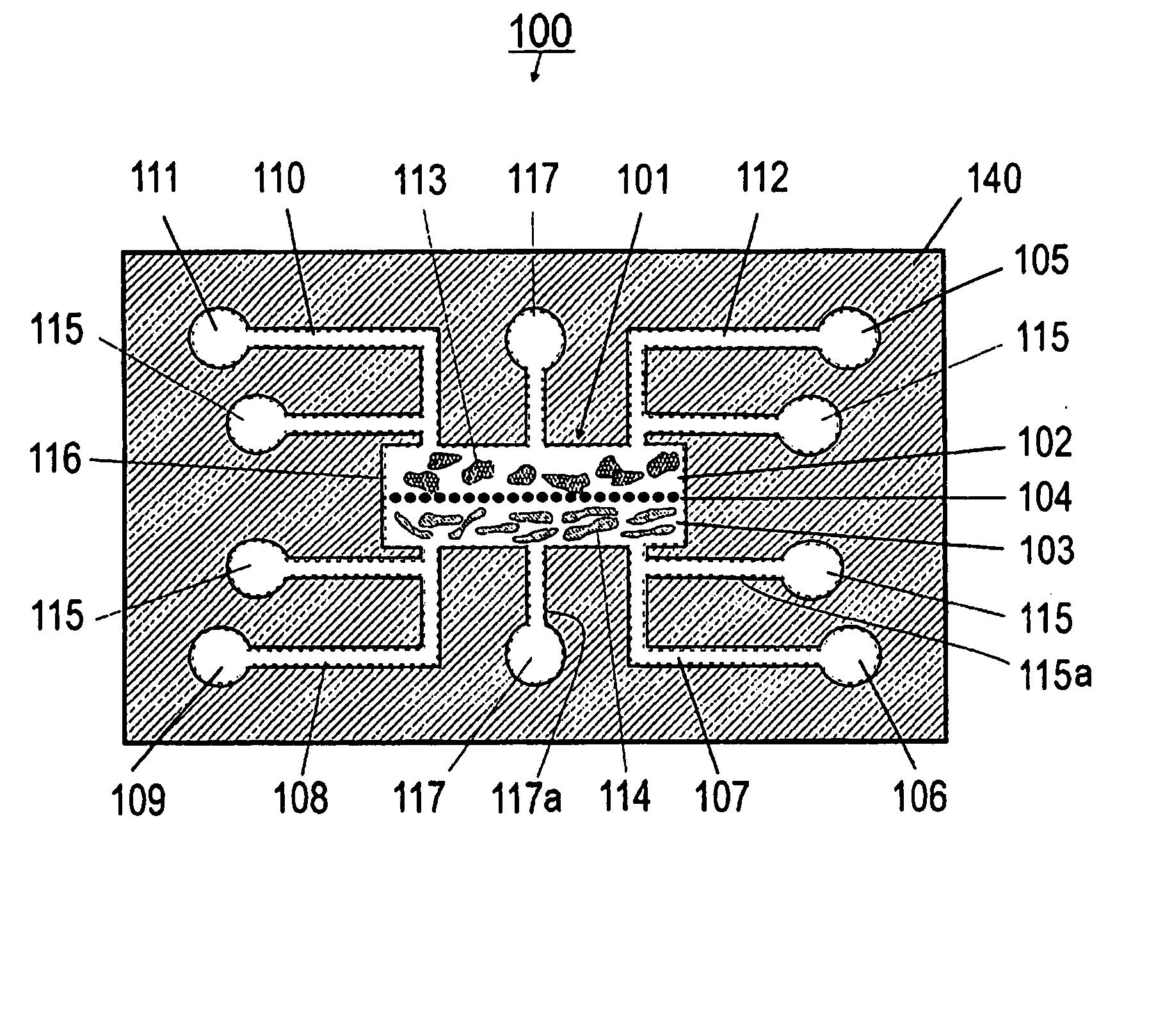
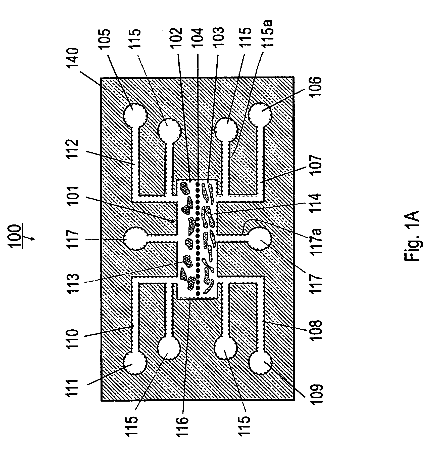
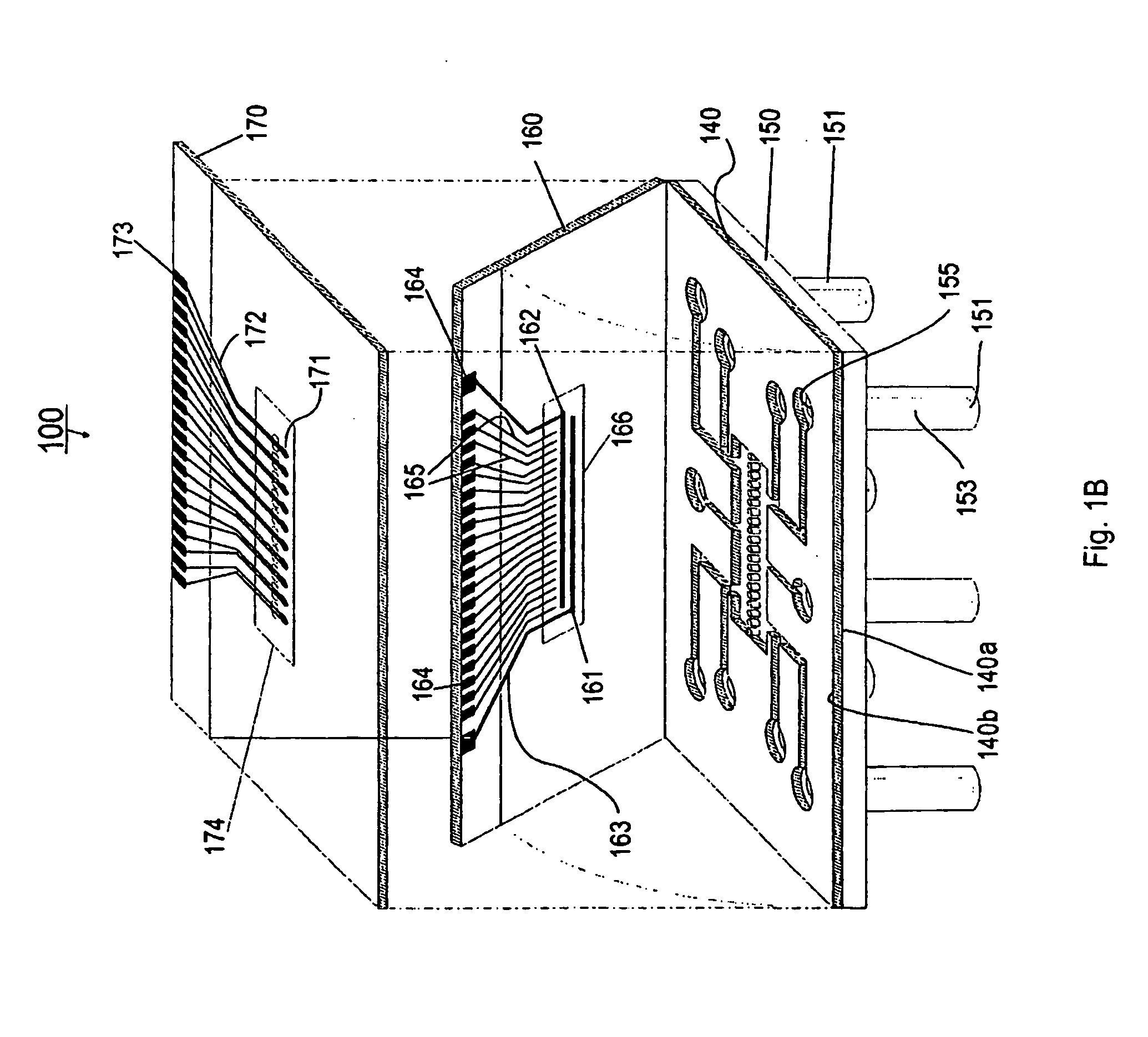
[0127] Referring now to FIGS. 1A and 1B, the present invention can be practiced in association with an inventive bioreactor 100 as shown in FIGS. 1A and 1B. In one embodiment, the bioreactor 100 includes a first substrate 140 having a first surface 140a and an opposite second surface 104b, defining a chamber 101 therebetween for receiving cells and a liquid medium. The bioreactor 100 has a barrier 104 dividing the chamber 101 into a first subchamber 102 and a second subchamber 103, wherein the barrier 104 has a porosity to allow the first subchamber 102 and the second subchamber 103 in fluid communication and allow at least one predetermined type of cells to permeate between the first subchamber 102 and the second subchamber 103. The porosity of the barrier 104 can also be chosen not to let any cells to permeate.

[0128] As formed, the first subchamber 102 is adapted for receiving a first type of material such as cells 113 and the second subchamber 103 is ...


PUM

PropertyMeasurementUnit
areaaaaaaaaaaa
diameteraaaaaaaaaa
diameteraaaaaaaaaa

Abstract

A bioreactor with substance injection capability. In one embodiment, the bioreactor includes a first substrate having a first surface, an opposite second surface and edges. The bioreactor further includes a second substrate having a first surface and an opposite second surface, defining a cavity with a bottom surface, where the bottom surface is located therebetween the first surface and the second surface. The first surface of the first substrate is received by the second surface of the second substrate to cover the cavity so as to form a chamber for receiving cells and a liquid medium. A port is formed in the second substrate between the bottom surface and the first surface of the second substrate. As formed, the port is in fluid communication with the chamber to allow a stream of substance to be introduced into the chamber. The stream of substance is controlled so as to provide a gradient, or a concentration gradient of the substance, to the chamber. The stream of substance includes a substance affecting the growth of cells such as chemokine.

Description

[0001] This application is being filed as a PCT International Patent application in the name of Vanderbilt University, a U.S. national corporation, applicant for the designation of all countries except the US, and John P. Wikswo and Franz J. Baudenbacher, both U.S. nationals and residents, applicants for the designation of the US only, on 27 Aug. 2003.[0002] The present invention was made with Government support under Grant No. N66001-01-C-8064 awarded by the Defense Advanced Research Projects Administration and the Office of Naval Research. The United States Government may have certain rights to this invention pursuant to these grants.[0003] Some references, which may include patents, patent applications and various publications, are cited in a reference list and discussed in the description of this invention. The citation and / or discussion of such references is provided merely to clarify the description of the present invention and is not an admission that any such reference is “p...

Claims


Application Information

Patent Timeline
Patent Type & Authority Applications(United States)
IPC IPC(8): C12M3/00C12M3/06
CPCB01L3/502723B01L3/502746B01L3/502761B01L2200/0668B01L2300/0645B01L2300/0681B01L2300/0816B01L2300/0887B01L2300/10B01L2400/0633B01L2400/086C12M23/16C12M25/14C12M29/04C12M29/10C12M35/08C12M41/46
Inventor WIKSWO, JOHNPBAUDENBACHER, FRANZJHASELTON, FREDERICKHOFMEISTER, WILLIAMHLIN, CHARLESPMCCAWLEY, LISAJSTREMLER, MARKAWEAVER, ALISSA
Owner VANDERBILT UNIV
Why Eureka
Try Eureka