
Data decoding method and circuit and information recording and reproducing apparatus using the same

a data decoding and reproducing circuit technology, applied in the field of high density information storage data decoding and reproducing methods, data decoding and reproducing circuits, information storing and reproducing apparatuses, etc., to achieve the effect of preventing the influence of data-dependent noise components, reducing the cost of data storage, and improving the accuracy of stochastic probability

Inactive Publication Date: 2006-07-13
WESTERN DIGITAL TECH INC
View PDF2 Cites 2 Cited by
  • Summary
  • Abstract
  • Description
  • Claims
  • Application Information

AI Technical Summary

Benefits of technology

The present invention provides a method to compensate for errors in data detection caused by non-stationary noise in high-density recording devices. The method uses a maximum likelihood data detection technique and identifies specific error patterns that occur frequently. By calculating the likelihood of occurrence of the error pattern and considering the effect of stochastic properties and distribution of media noise, the method improves the precision of identifying the error event and prevents its influence on the data-dependent noise component. This results in a more reliable data demodulation process for the conventional PRML data demodulation technique.

Problems solved by technology

In addition, that is caused because the discrimination margin of the signal sequence with respect to noise variation depends on sum of the squared errors between the reproduced signal sequence the correct data code sequence has and the reproduced signal sequence the error data code sequence has.
In other words, it can be said that the error event that frequently occurs in the maximum likelihood data detection has an error pattern that decreases the sum of the squared errors between the reproduced signal sequences for the correct data sequence and for the error data sequence.

Method used


Image

  • Data decoding method and circuit and information recording and reproducing apparatus using the same
  • Data decoding method and circuit and information recording and reproducing apparatus using the same
  • Data decoding method and circuit and information recording and reproducing apparatus using the same

Examples


Embodiment Construction

[0019] Embodiments of the present invention will now be described with reference to the accompanying drawings.

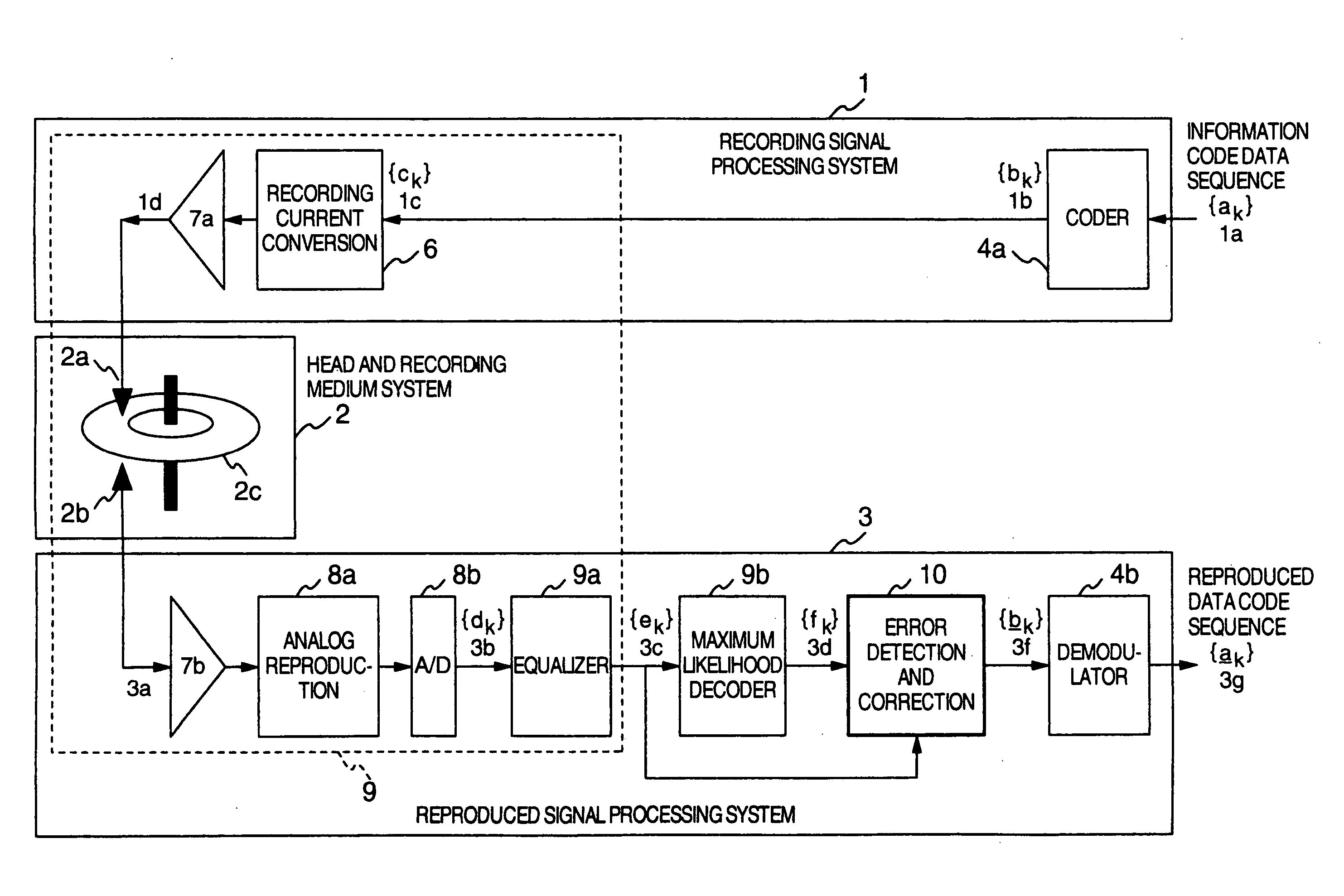
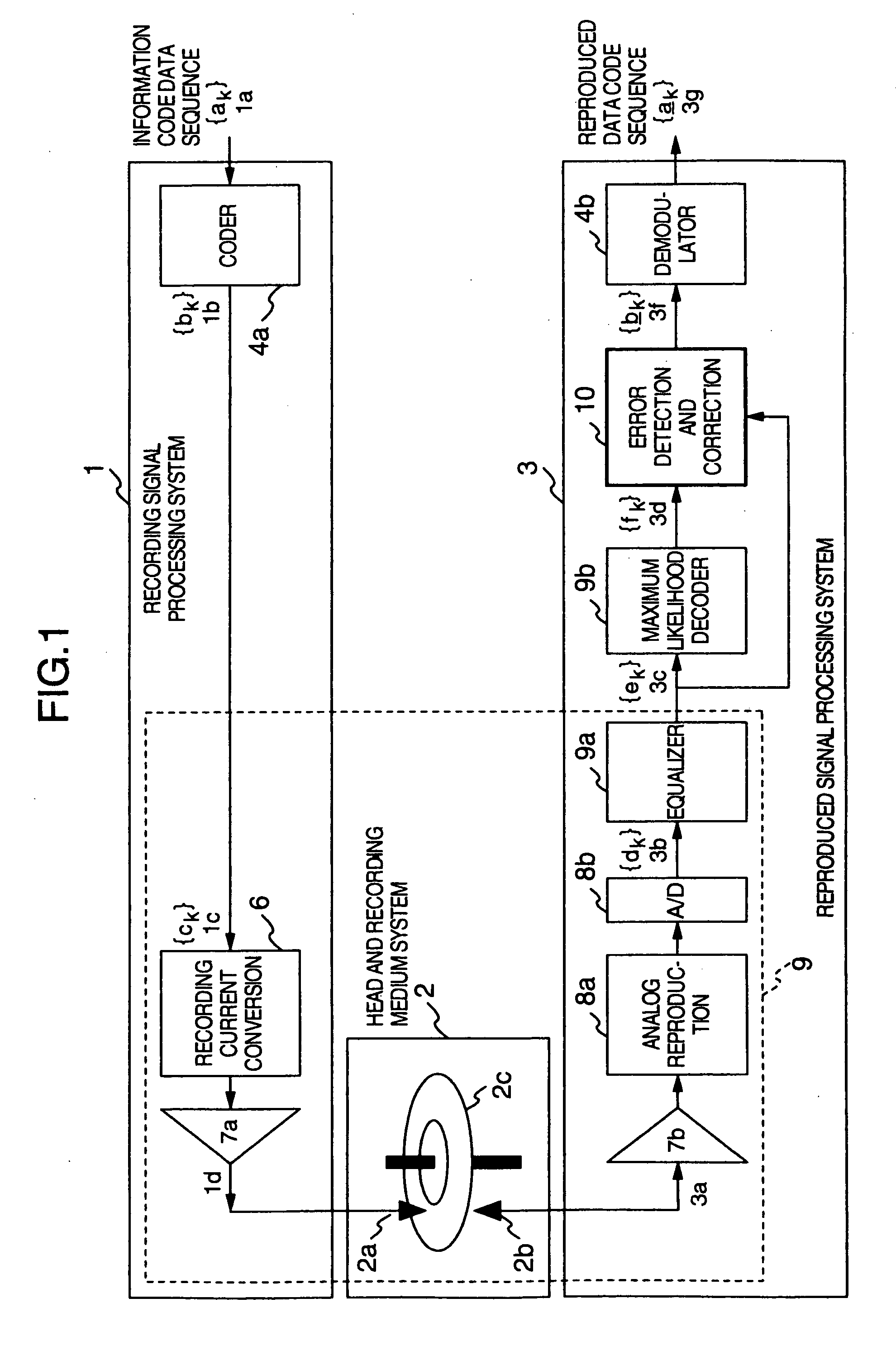
[0020]FIG. 1 shows a basic configuration of an information recording and reproducing system to which the present invention is applied. As shown in FIG. 1, the information 10 recording and reproducing system of the present embodiment includes a recording signal processing system 1, a head and recording medium system 2, and a reproduced signal processing system 3. The invention contemplates improving the reliability of recorded information reproduction in a signal processing system, especially in the reproduced signal processing system 3. This data recording and reproducing method can be applied to the head and recording medium system 2 based upon various recording and reproducing principles such as magnetic, optical or magneto-optical recording. Supposing especially a magnetic recording and reproducing system represented by a magnetic disk apparatus, the embodiment will now ...


PUM

PropertyMeasurementUnit
lengthaaaaaaaaaa
densityaaaaaaaaaa
recording densityaaaaaaaaaa

Abstract

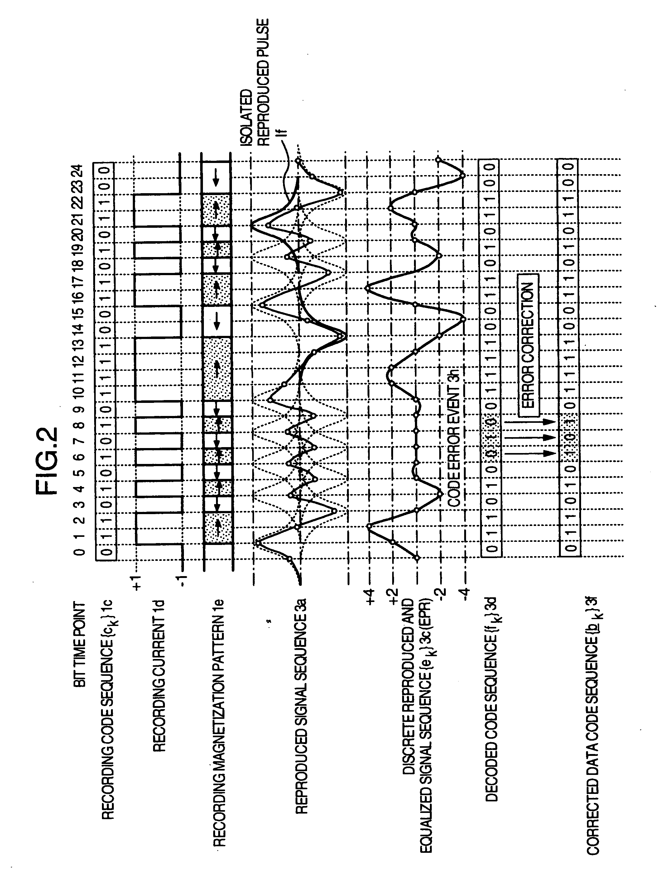
In a partial-response maximum-likelihood (PRML) signal detection and processing technique, reduction of data detection error events caused due to medium noise is achieved. For a PRML detection data result obtained after PRML data demodulation, a code error event that depends on a signal distance, and which has a high frequency of occurrence, is noticed and its occurrence probability is estimated. A locally-existing medium noise quantity is estimated from preceding and subsequent code patterns of the PRML detection data result. Based on this, the occurrence probability of the error event is compensated to improve the detection precision. As a result, data modulation with reliability higher than conventional maximum likelihood detection can be realized with a simple circuit structure.

Description

[0001] This application is a divisional application of U.S. application Ser. No. 10 / 206,211, which was allowed on Nov. 15, 2005, the entirety of which is incorporated herein by reference.BACKGROUND OF THE INVENTION [0002] The present invention relates to a data decoding and reproducing method for high density information storage, and a data decoding and reproducing circuit and an information storing and reproducing apparatus for implementing such a method. [0003] In implementing high density information storage, it is demanded to demodulate recorded information data from a signal reproduced from a recording medium, with high reliability. In high density magnetic recording and reproducing apparatuses represented by magnetic disk drive apparatuses, data demodulation with high reliability becomes difficult. Because an increase of intersymbol interference and a remarkable degradation in signal quality, i.e., signal-to-noise ratio is caused in the reproduced signal as the recording densi...

Claims


Application Information

Patent Timeline
Patent Type & Authority Applications(United States)
IPC IPC(8): H03M13/03G11B5/012G11B5/09G11B20/14G11B20/18H03M13/45
CPCG11B5/012G11B5/09G11B20/10055G11B20/1403G11B20/18
Inventor SAWAGUCHI, HIDEKINISHIDA, YASUTAKAMOCHIZUKI, MASAFUMITSUCHINAGA, HIROYUKI
Owner WESTERN DIGITAL TECH INC
Learn More