
Gateway power synchronization

a power synchronization and gateway technology, applied in television systems, high-level techniques, instruments, etc., can solve the problems of waste of bandwidth on the distribution line feeding the distribution center, single button, additional problem, etc., and achieve the effect of reducing the bandwidth utilization of bandwidth and reducing the bandwidth of the distribution lin

Inactive Publication Date: 2006-07-13
QWEST
View PDF37 Cites 8 Cited by
  • Summary
  • Abstract
  • Description
  • Claims
  • Application Information

AI Technical Summary

Benefits of technology

"The present invention provides a system for receiving networked video with power control for gateways and receivers. The system includes a remote control that sends a power control input signal to a gateway, which then decodes or transforms the signals and sends a predefined channel to the receiver. The gateway can also switch to an off state based on the power control input and reduce bandwidth requirements in a switched video distribution network. The technical effects of the invention include convenient recovery, greater functionality in the off state, and reduced distribution line bandwidth requirements."

Problems solved by technology

While this simplifies equipment operation, the use of a single button can create problems in certain circumstances.
In addition to creating a potentially puzzling situation for the customer, turning the receiver off while leaving the gateway on and switched to the last channel viewed by the customer creates an additional problem.
This wastes bandwidth on the distribution line feeding the distribution center if no other customer serviced by the distribution center is also viewing the same channel.

Method used


Image

  • Gateway power synchronization
  • Gateway power synchronization
  • Gateway power synchronization

Examples


Embodiment Construction

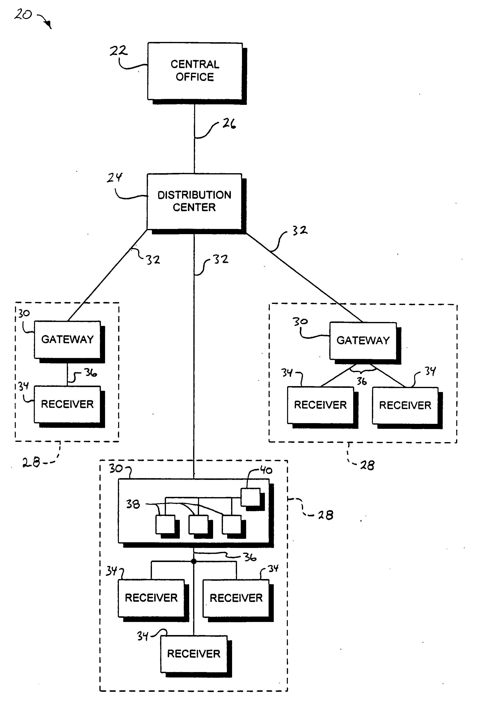
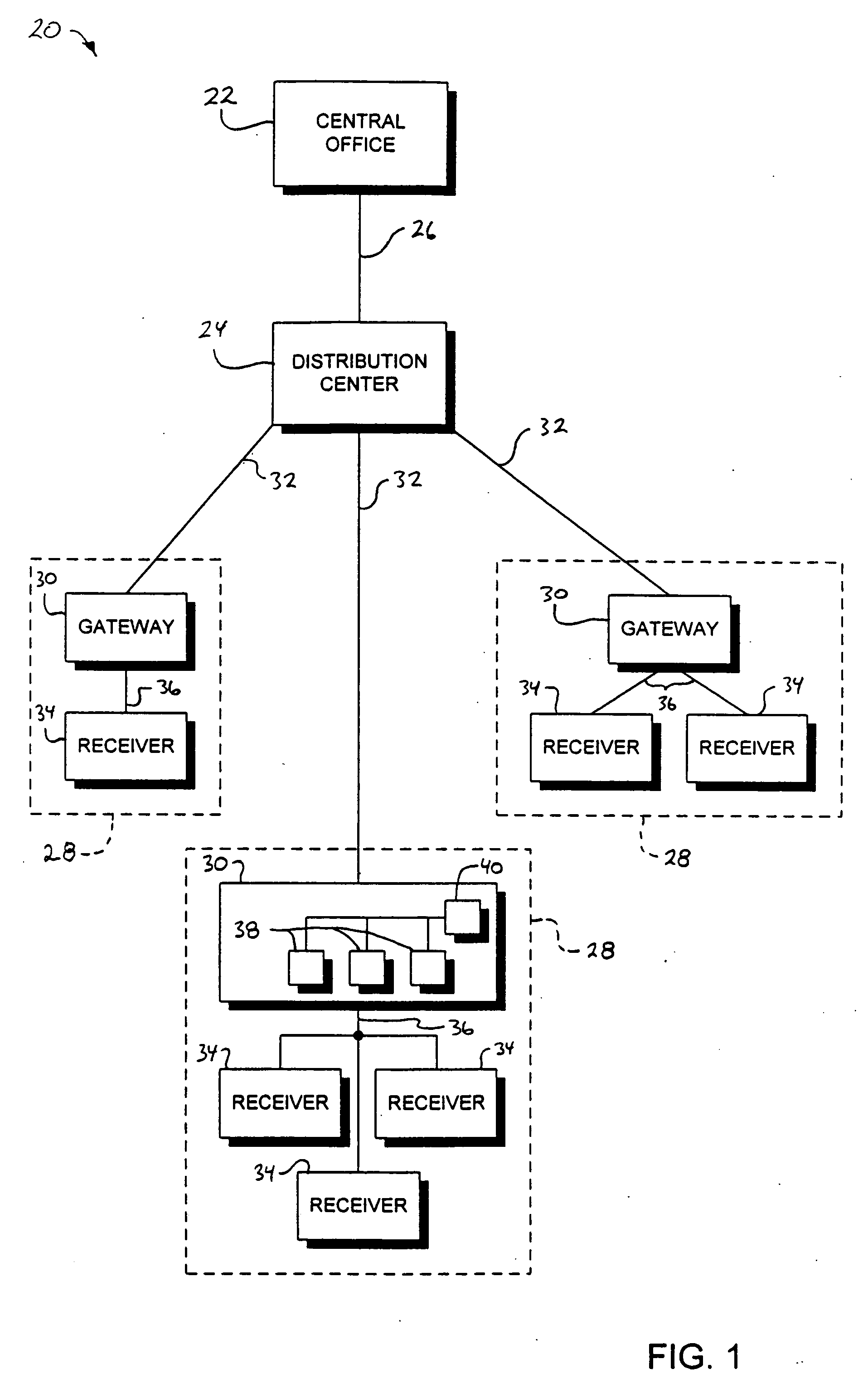
[0019] Referring to FIG. 1, a block diagram illustrating a video distribution network according to an embodiment of the present invention is shown. A video distribution network, shown generally by 20, includes at least one central office 22 generating or supplying video content signals. Distribution centers, one of which is indicated by 24, are connected to central office 22 through distribution line 26. Distribution center 24 services a plurality of customer sites 28. Each customer site 28 includes gateway 30 for receiving network signals 32 from distribution center 24. Customer site 28 also includes one or more receivers 34 receiving video signals 36 from gateway 30. Receiver 34 may be a television, computer, video recording device, or the like.

[0020] Gateway 30 decodes or transforms network signals 32 to produce video signals 36 in a format acceptable by receiver 34. Formats include analog, digital, HDTV, and the like. Gateway 30 may include one or more gateway sources 38, each ...


PUM


Abstract

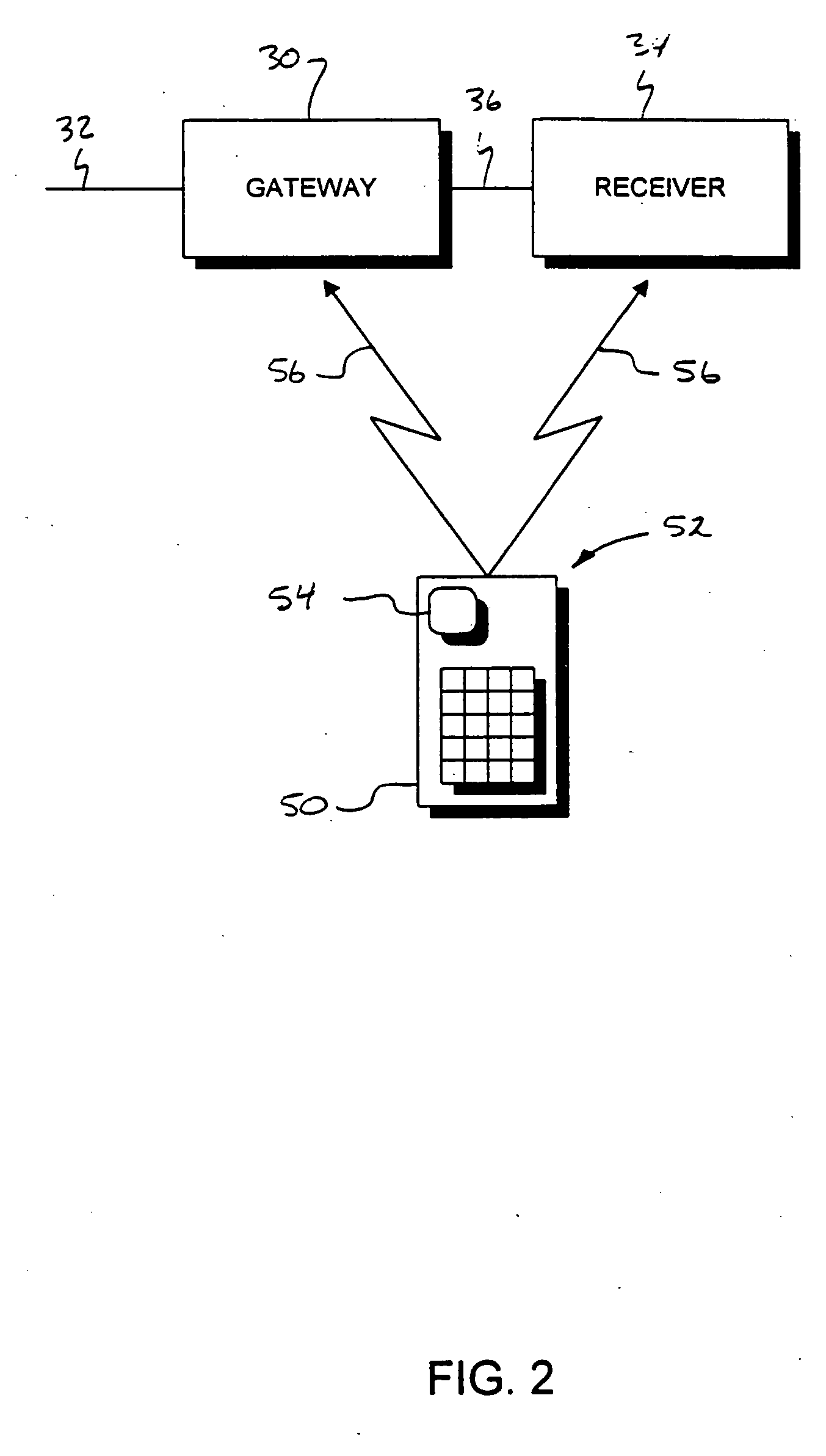
A system for receiving network video includes a remote control with a power control input. A video receiver, controlled by the remote control, powers up or powers down based on a control signal indicating activation of the power control input. The video receiver receives video signals from a gateway or gateway source connected to the video network. The gateway decodes signals received from the network into a format acceptable by the receiver. If the gateway receives a control signal from the remote control indicating activation of the power control input and the gateway is currently in the “on” state, the gateway toggles to the “off” state and outputs a predefined channel to the receiver.

Description

TECHNICAL FIELD [0001] The present invention relates to gateways in video distribution networks. BACKGROUND ART [0002] Video distribution networks deliver entertainment and educational content from one or more central locations to many customer premises. The video distribution network includes distribution centers, with each distribution center serving a cluster of customer locations. If the video distribution system is a broadcast system, the bandwidth requirements of distribution lines feeding distribution centers remains fairly constant over short time intervals. If the video distribution system is switched, video signals received by the distribution center depend, in part, on the demand generated by serviced customers. [0003] Each customer premise includes a gateway connected to the servicing distribution center. The gateway receives network signals from the distribution center and forwards video signals to one or more video receivers at the customer location. The gateway may mo...

Claims


Application Information

Patent Timeline
Patent Type & Authority Applications(United States)
IPC IPC(8): H04N7/173H04L12/10H04L12/12H04N7/088H04N7/10H04N7/16H04N21/41H04N21/422H04N21/443H04N21/488
CPCH04L12/10H04L12/12H04N7/088H04N7/10H04N7/106H04N7/16H04N7/163H04N21/4104H04N21/42204H04N21/4432H04N21/4882Y02B60/34Y02D30/50H04N21/4112
Inventor CAMPBELL, KURT A.
Owner QWEST
Learn More