Lubricated hot rolling method

a hot rolling method and lubricating oil technology, applied in the direction of lubricant composition, manufacturing tools, profile control devices, etc., can solve the problems of deterioration of manufacturing efficiency, lubricating oil supplied in the form of emulsified lubrication may become not easily adhesionable to the rolls, and possible slippage and rolling slippag

Active Publication Date: 2006-07-20
ARCELORMITTAL INVESTIGACION Y DESARROLLO SL +1
View PDF0 Cites 4 Cited by
  • Summary
  • Abstract
  • Description
  • Claims
  • Application Information

AI Technical Summary

Benefits of technology

[0010] It is one of the objects of the present invention to provide a safe and stable lubricated hot rolling method not causing any fire accident, when a lubricating oil which is added with one kind or two or more kinds among high-basic alkaline-earth metal phenate, high-basic alkaline-earth metal carboxylate, high-basic alkaline-earth metal salicylate, high-basic alkaline-earth metal sulfonate, and the like, is supplied by, e.g., the gas atomizing method.
[0011] According to one exemplary embodiment of the present invention, it is possible to perform a safe and stable lubricated hot rolling while preventing fire from occurring even if a lubricating oil is supplied by the gas atomizing method in which the high-basic alkaline-earth metal compound of relatively high viscosity is blended, with the following exemplary conditions:
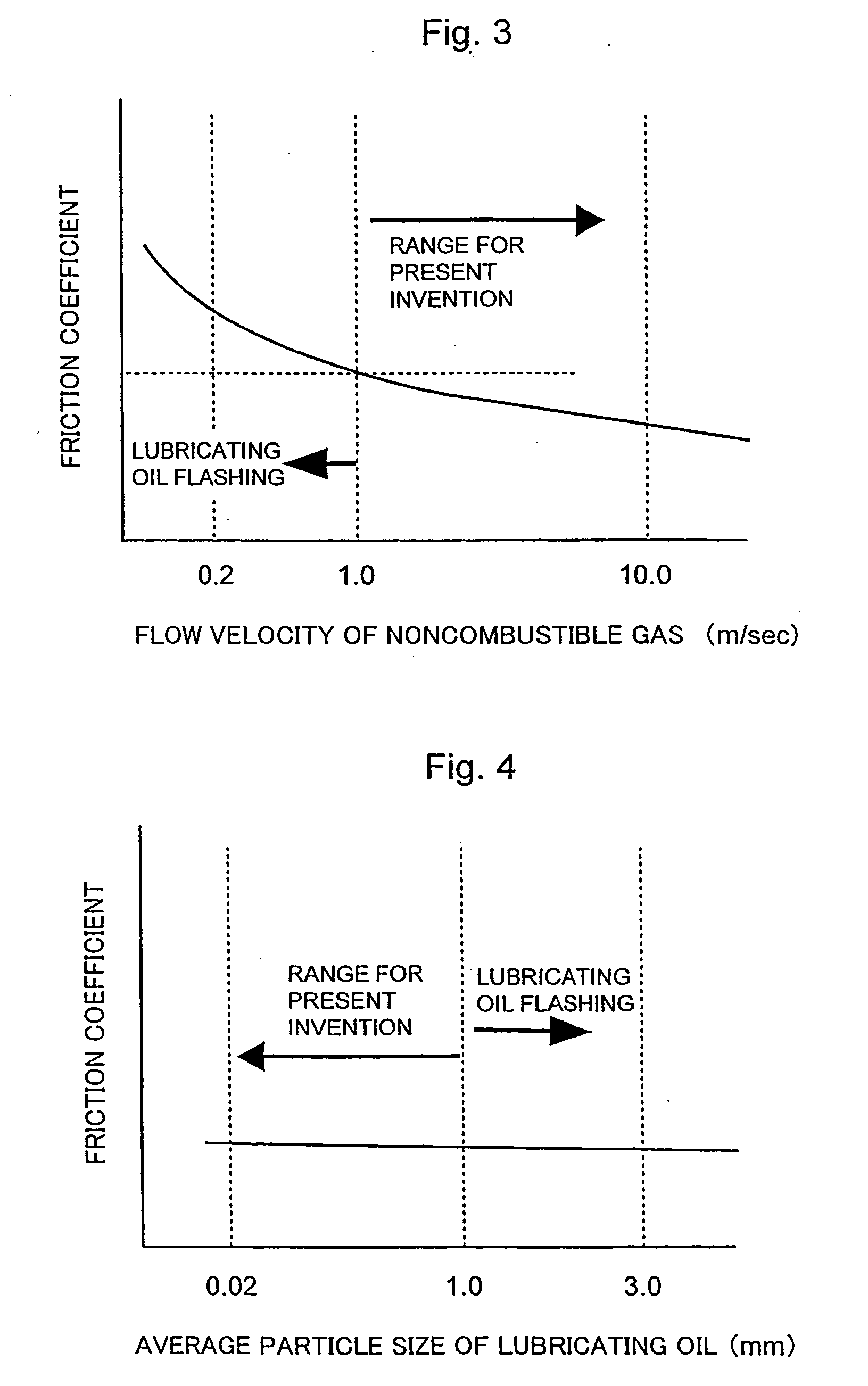
[0027] The lubricating oil can be granulated into particulates having a size less than 1 mm, because lightening the weight of the lubricating oil drop allows most of the lubricating oil sprayed from the nozzle to reach the rolls by the airflow of the noncombustible gas. If a lubricating oil whose particulates have a size of 1 mm or more is sprayed, the lubricating oil, particularly that sprayed from the lubricating nozzle for the upper roll, may become easily droppable to the steel material, igniting by the heat of the steel material, and leading to likelihood of flashing of the oil adherent to the surface of the facilities provided near an edge portion of the steel material. If the particulate size is less than 1 mm, e.g., virtually no lubricating oil drops from the nozzle, and even if it ignites, its volume is small enough that it immediately burns out, and does not spread to other parts.
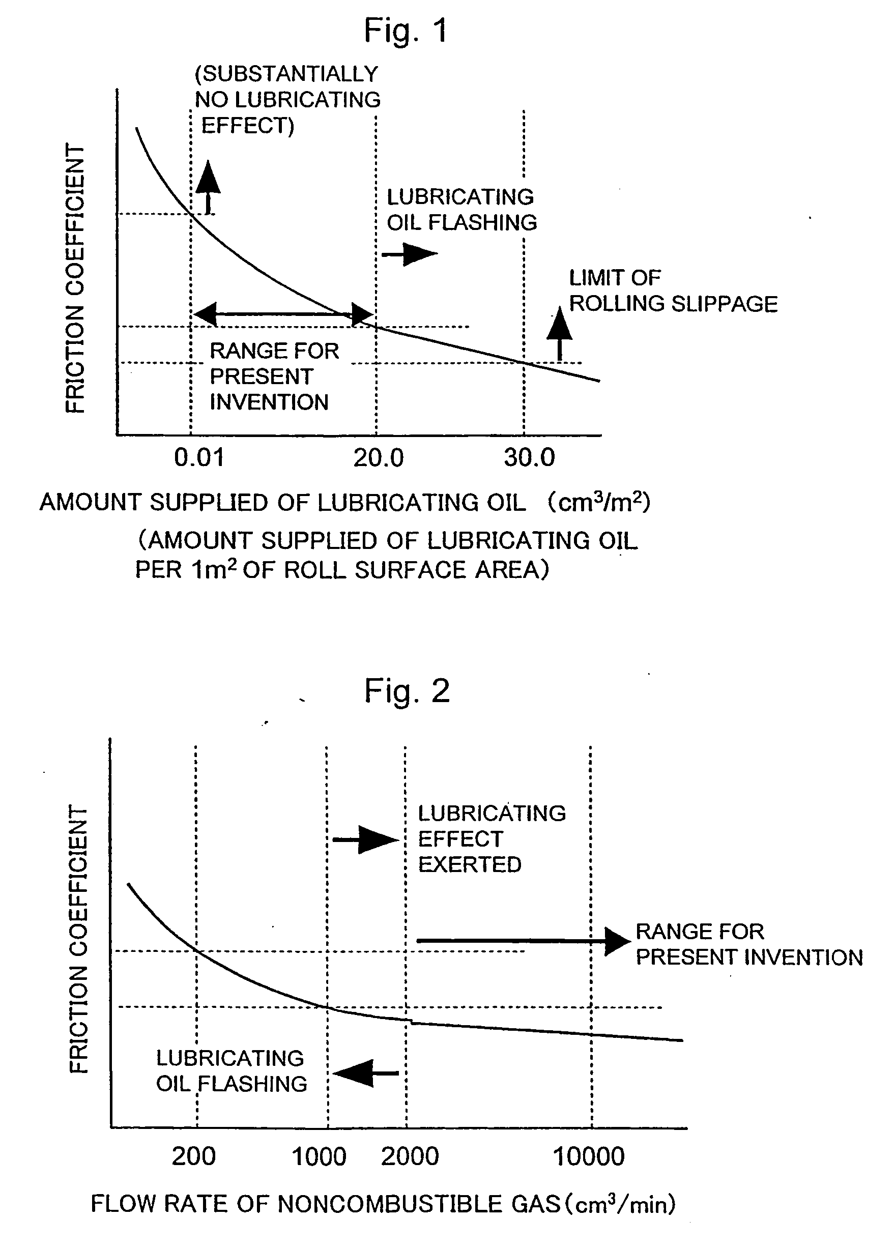
[0030] By making the flow velocity of the noncombustible gas 1 m or higher per second, the speed of the lubricating oil sprayed from the nozzle is made high, and the time from spraying the lubricating oil out of the nozzle up to reaching thereof to the rolls can be shortened. This substantially enhances the effect of preventing the sprayed lubricating oil from scattering to somewhere other than the roll surface. By increasing the flow rate while leaving the flow velocity to less than 1 m per second encourages additional scattering of the lubricating oil in the form of particulates to somewhere other than the rolls. Unless both the flow rate and flow velocity are appropriately set out, the phenomenon that the lubricating oil scatters and is deposited on facilities other than the roll surface may occur frequently. In addition, if the gas flow velocity is higher, the effect of blowing out the flame which has ignited near the rolls can be enhanced. Both the gas flow rate and the gas flow velocity being made high can be very effective in preventing the flame from being created and in extinguishing a flame caused, and forms an important element of the present invention.
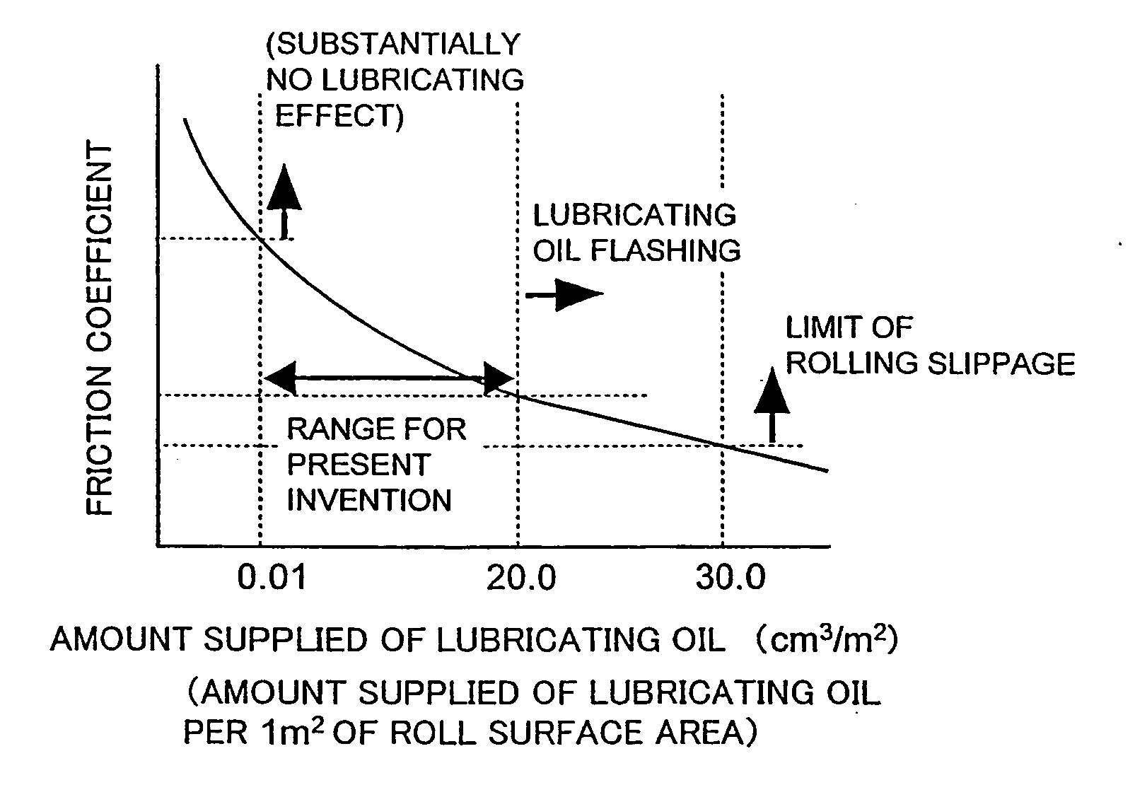
[0031] If the maximum amount supplied of the lubricating oil exceeds 20 cm3 per 1 m2 of the area of the roll surface, the lubricating effect is improved, but the supply becomes excessive, and in some instances leads to the lubricating oil spilling out of the plate path, blown out of the rolls with the centrifugal force by the rolling of the rolls, and scattering to and being deposited on the facilities around the rolls. This can become the origin of the fire, leading to higher probability of occurrence of fire accident. In the amount of 20 cm3 or less, most of the lubricating oil sprayed to the rolls is guided into the roll bite, consumed by the friction between the rolls and the steel material, so that it does not turn into the origin of the fire. In addition, with an amount of the lubricating oil of 0.01 cm3 or more per 1 m2, a bit slippage can be prevented. Further, if the amount supplied of the lubricating oil is more than 30 cm3 per 1 m2 of the roll surface area, the rolling slippage occurs under any rolling condition, so that the amount supplied should be that volume or less. Thus, an amount supplied exceeding 30 cm3 per 1 m2 of the roll surface area can cause a fire accident, and it may be difficult to safely perform hot rolling. If the operation is performed preferably with the amount of the lubricating oil to be supplied being in a range of 0.1 cm3 to 15 cm3 per 1 m2 of the roll surface area, it may be effective from the aspect of lubricity, economical efficiency, and safety.
[0032] According to an exemplary embodiment of the present invention, when a lubricating oil being added with one kind or two or more kinds among the high-basic alkaline-earth metal phenate, high-basic alkaline-earth metal carboxylate, high-basic alkaline-earth salicylate, or high-basic alkaline-earth metal sulfonate is supplied by the gas atomizing method to perform lubricated rolling, it generally does not cause bit slippage, rolling slippage, and the like, while a lubricating effect of the same or higher level compared to conventional lubrication supply methods can be brought out, and at the same time a safe and stable lubricated rolling can be performed without causing fire.

Problems solved by technology

Furthermore, in the hot rolling, a plate is thicker than in cold rolling, and a feeding device of a material may not be provided, so that bit slippage and rolling slippage may likely occur.
Accordingly, frequent cleaning of the pipe and nozzle may be required, which can lead to a deterioration of manufacturing efficiency.
However, when the roll cooling water leaks into the lubrication supplying section through a clearance made by the rotation of the rolls and abrasion of the wiper, the lubricating oil supplied in the form of emulsified lubrication may become not easily adherable to the rolls.
This can occur because the roll cooling water that leaks forms a water film over the surface of the roll, and further, the emulsion is blended with the cooling water so that its concentration (amount of the lubricating oil to water) is reduced, and the lubricating effect becomes difficult to be obtained.
It is known that approximately the same problem occurs with a supplying method in a steam-atomizing form.
However, the concentration may be constantly changing by the dirt within the lubricant piping system, clogging of the nozzle, and further, a slight difference of viscosity of the lubricating oil by changing of temperature and humidity.
A consequent problem that variation of lubricating effect occurs may also be recognized.
However, in this method, the lubricating oil itself can be directly supplied to the rolls near a steel material heated to approximately 800° C. to 1200° C., so that depending on the physicality and the usage environment of the lubricating oil, fire may break out in some instances.

Method used


Image

  • Lubricated hot rolling method
  • Lubricated hot rolling method
  • Lubricated hot rolling method

Examples


first exemplary embodiment

[0042] A controlling effect of generation of a mill scale of rolls according to the present invention is reviewed, and and a determination is made as to whether flashing phenomenon occurs or not during experiments, e.g., by using a hot rolling friction testing machine.

[0043] Experimental piece: diameter 80 mm, width 10 mm, [0044] made of an HSS roll material

[0045] Counterpart piece: diameter 165 mm, width 15 mm, [0046] made of S45C

[0047] Load: 30 kgf

[0048] Rotational speed of experimental piece: 176 m / min

[0049] Speed of counterpart piece: 185 m / min

[0050] Temperature of friction surface of experimental piece: 650° C.

[0051] Temperature of friction surface of counterpart piece: 880° C.

Exemplary Lubricating Oil:

[0052] (a) A lubricating oil in which 15 vol % of calcium sulfonate having a basicity of 300 mgKOH / g is blended in a mineral oil, and whose viscosity at 40° C. is 110 cSt.

[0053] (b) A lubricating oil in which 15 vol % of a colza oil is blended in a mineral oil and whos...

second exemplary embodiment

[0064] It is possible to use a 2Hi rolling mill (2-high mill) to examine a lowering effect of friction coefficient serving as a representative indicator of the lubricating performance when the lubricating-oil-supplying conditions were changed, and at the same time examined, by a rolling experiment, a marginal condition of occurrence of ignition. In this exemplary experiment, base conditions in accordance with the exemplary embodiment of the present invention with respect to four kinds of supply conditions were provided, and on the basis thereof, a lowering effect of the friction coefficient and occurrence of an ignition phenomenon were investigated by changing each condition of the four kinds of conditions separately.

[0065] Roll: diameter 400 mm, HSS roll, roll length 100 mm

[0066] Material to be rolled: 0.02% carbon steel, thickness 1 mm×width 50 mm×length 1000 m (coil)

[0067] Heating temperature: 1000° C. (nitrogen atmosphere)

[0068] Rolling speed: 50 m / min

[0069] Roll gap: 20% t...


PUM

PropertyMeasurementUnit
flow velocityaaaaaaaaaa
sizeaaaaaaaaaa
particulate sizeaaaaaaaaaa

Abstract

An exemplary lubricated hot rolling method is provided which can use a lubricating oil containing, e.g., one or more kinds among an high-basic alkaline-earth metal phenate, high-basic alkaline-earth metal carboxylate, high-basic alkaline-earth salicylate, or high-basic alkaline-earth metal sulfonate having a basicity of 40 mgKOH / g or higher, and has a viscosity at 40° C. of 800 cSt or less. The rolling can be performed by granulating or atomizing the lubricating oil into particulates whose average size is less than 1 mm, supplying the lubricating oil to rolls by using a noncombustible gas whose flow rate is 2000 cm3 or more per minute per lubricating nozzle. The velocity of the oil may be 1 m or more per second. The amount supplied of the lubricating oil can be controlled to 0.01 cm3 or more and 20 cm3 or less per 1 m2 of a surface area of the rolls.

Description

CROSS REFERENCE TO RELATED APPLICATION(S) [0001] This application is a national stage application of PCT Application No. PCT / JP2004 / 008152 which was filed on Jun. 4, 2004 and published on Dec. 15, 2004 as International Publication No. WO 2004 / 108312 (the “International Application”), the entire disclosure of which is incorporated herein by reference. This application claims priority from the International Application pursuant to 35 U.S.C. § 365. The present application also claims priority under 35 U.S.C. § 119 from Japanese Patent Application No. 2003-162490, filed Jun. 6, 2003, the entire disclosure of which is incorporated herein by reference.FIELD OF THE INVENTION [0002] The present invention generally relates to a hot rolling method using a lubricating oil in a hot rolling step of a steel manufacturing process. In particular, the present invention relates to a method to safely perform lubricated rolling by preventing fire accident which can occur by exposing a lubricant oil to ...

Claims


Application Information

Patent Timeline
Patent Type & Authority Applications(United States)
IPC IPC(8): B21B45/02B21B27/10C10M159/20C10M159/22C10M159/24
CPCB21B27/10B21B45/0242C10M159/20C10M159/22C10M159/24C10N2230/02C10N2230/52C10N2240/404C10N2030/02C10N2030/52C10N2040/242B21B45/0245B21B15/005B21B37/44
Inventor INOUE
Owner ARCELORMITTAL INVESTIGACION Y DESARROLLO SL
Why Eureka
Try Eureka