Rotation sensing apparatus and method for manufacturing the same

Inactive Publication Date: 2006-07-20
IND TECH RES INST
View PDF6 Cites 5 Cited by
  • Summary
  • Abstract
  • Description
  • Claims
  • Application Information

AI Technical Summary

Benefits of technology

[0006] The primary objective of the present invention is to provide a rotation sensing apparatus and method for manufacturing the same, in which measuring rotations of multiple axes can be achieved by utilizing symmetrical structure combination.
[0007] The secondary objective of the present invention is to provide a rotation sensing apparatus and method for manufacturing the same such that the apparatus can be manufactured by MEMS process technology. The invention utilizes symmetrical structure combination to generate effect of resonance for reducing power consumption of elements and reducing electrostatic driving voltage.
[0008] Another objective of the present invention is to provide a rotation sensing apparatus and method for manufacturing the same, in which a structural design is utilized such that center of mass of the apparatus will not change when the apparatus is driven and thus noise disturbance is reduced.
[0012] To make the examiner easier to understand the objectives, structure, innovative features, and function of the invention, preferred embodiments together with accompanying drawings are illustrated for the detailed description of the invention.

Problems solved by technology

However, traditional gyroscopes have problems of with complicated structure and been fast wear and tear such that traditional gyroscopes have short usage of life, expensive price and heavy weight.
However, the center of mass of the cantilever structure will change continuously due to vibration of the cantilever beam, so that noise will occurs to disturb the measured results.
However, the structures disclosed in the above-mentioned two patents can not be minified by MEMS process technology even if they can solve the problem of changing center of mass due to asymmetric structure.

Method used


Image

  • Rotation sensing apparatus and method for manufacturing the same
  • Rotation sensing apparatus and method for manufacturing the same
  • Rotation sensing apparatus and method for manufacturing the same

Examples


Embodiment Construction

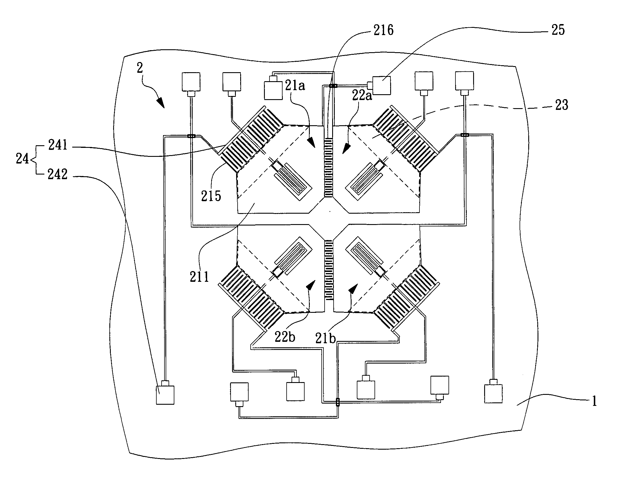
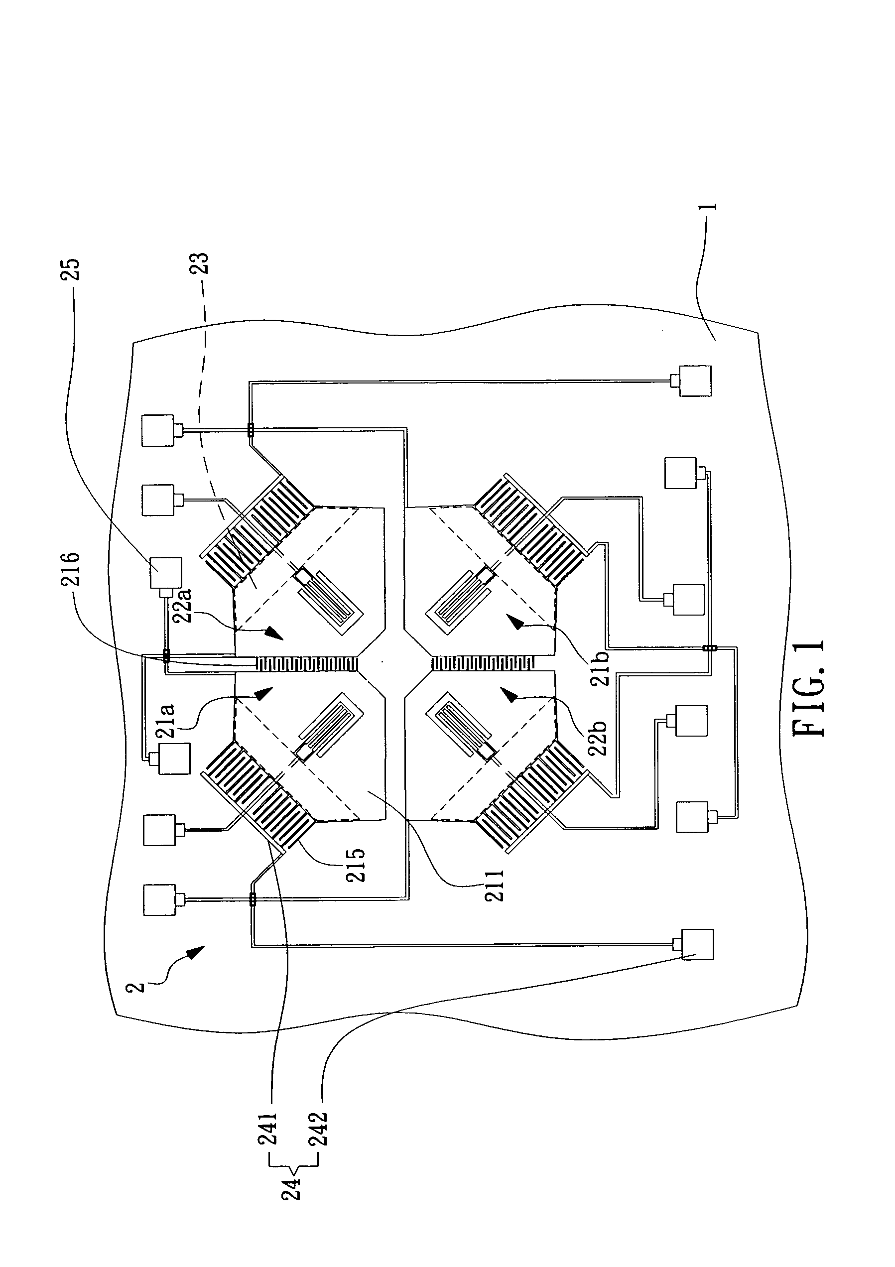
[0019]FIG. 1 is a diagram of a preferred embodiment of a rotation sensing apparatus of the present invention. The rotation sensing apparatus 2 comprises a first pair of vibration parts 21a and 21b, a second pair of vibration parts 22a and 22b, and a sensing electrode 23. The structure of the first pair of vibration parts 21a and 21b is the same with the one of the second pair of vibration parts 22a and 22b. The first pair of vibration parts 21a and 21b and the second pair of vibration parts 22a and 22b are disposed on a substrate 1 symmetrically and are away from the substrate 1 with an appropriate distance (not shown). The first pair of vibration parts 21a and 21b is orthogonal to the second pair of vibration parts 22a and 22b.

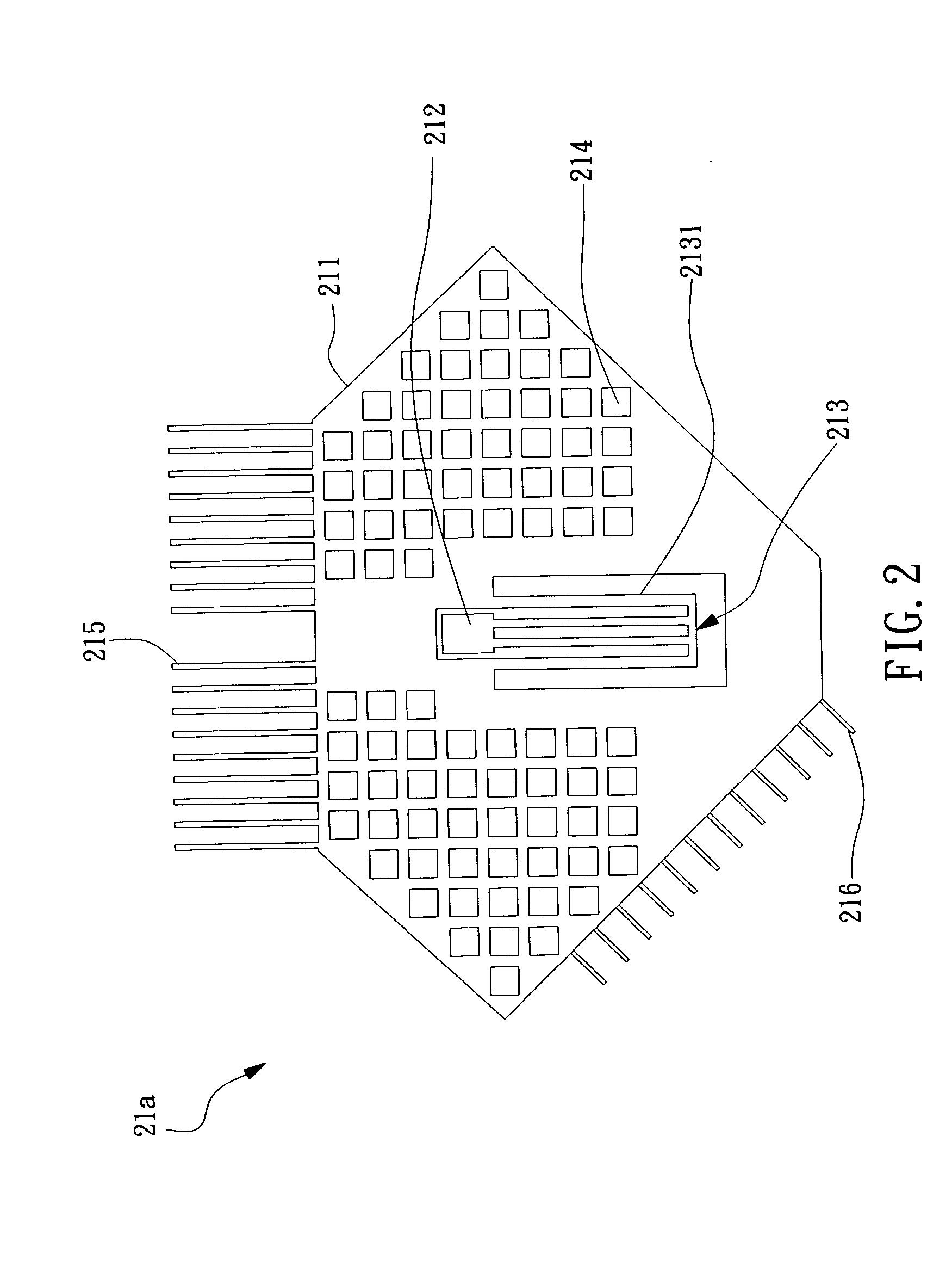
[0020]FIG. 2 is a diagram of a vibration part of the preferred embodiment of a rotation sensing apparatus of the present invention. The vibration part 21a comprises a electrostatic vibrating body 211, a fixed support 212, an elastic body 213, a plurality of ...


PUM


Abstract

The invention provides a rotation sensing apparatus and method for manufacturing the same, in which the rotation sensing apparatus comprises at least a pair of vibration parts and a sensing electrode. The pair of vibration parts is disposed on a substrate symmetrically and each vibration part comprises an electrostatic vibrating body, a fixed support and an elastic body. The electrostatic vibrating body is away from the substrate with an appropriate distance. The fixed support connects with the electrostatic vibrating body and the substrate. The elastic body connects the fixed support with some rods thereof and connects with the electrostatic vibrating body with some other rods thereof. The sensing electrode is disposed on the substrate and under the at least pair of vibration parts. The pair of vibration parts can vibrate horizontally by electrostatic force and will sway vertically to the substrate by Coriolis force when a rotation occurs. The rotation can be measured by detecting the change of capacitance between the electrostatic vibrating body and the sensing electrode.

Description

1. FIELD OF THE INVENTION [0001] The present invention relates to a rotation sensing apparatus and method for manufacturing the same, more particularly to a rotation sensing apparatus for measuring rotations of multiple axes and method for manufacturing the same, in which the vibrating structure body is formed in the manufacturing process and has a stable center of mass. 2. BACKGROUND OF THE INVENTION [0002] Gyroscope is an inertial sensing element and mainly measures angular velocity of a rotation by law of inertia. Traditional gyroscopes work by utilizing conservation law of angular momentum and are mainly applied for navigation in the fields of military, aeronautics and sailing. However, traditional gyroscopes have problems of with complicated structure and been fast wear and tear such that traditional gyroscopes have short usage of life, expensive price and heavy weight. [0003] By developments of consumer industry, the demands of gyroscopes with light weight, cheap price and lon...

Claims


Application Information

Patent Timeline
IPC IPC(8): G01P9/04H01L21/465
CPCG01C19/5719
Inventor KAI-CHENG, CHANGPEI-FANG, LIANGMING-HSIU, HSUYI-RU, CHENYA-PING, CHEN
Owner IND TECH RES INST
Why Eureka
Try Eureka