Ultrasonic flow meter including guide elements

a technology of ultrasonic flow meters and guide elements, which is applied in the direction of volume/mass flow measurement, measurement devices, instruments, etc., can solve the problems of interfering signal contributions, unable to fit the surface of ultrasonic transducers, and 1 must be sufficiently small

Inactive Publication Date: 2006-07-20
ROBERT BOSCH GMBH
View PDF1 Cites 42 Cited by
  • Summary
  • Abstract
  • Description
  • Claims
  • Application Information

AI Technical Summary

Benefits of technology

[0015] Furthermore, the described system may also be entirely or partly integrated into an insertion sensor which may be used in the flow pipe. In this connection, in particular, one or multiple ultrasonic transducers as well as an electronic control unit may be integrated into the insertion sensor for activating and / or reading out at least one ultrasonic transducer. The electronic control unit for reading out at least one ultrasonic transducer may, for example, contain electronics for preprocessing received signals. Appropriate electronic plug-and-socket connections may also be integrated for contacting the insertion sensor. Furthermore, at least one reflection element having a reflection surface may be integrated into the insertion sensor, making it possible to implement, for example, one of the reflection systems described above. Advantageously, the at least one reflection element is inserted into the flow pipe in such a way that fluid is able to flow on both sides of the reflection surface along the reflection body. This has the advantage in particular that if the reflection element is not in contact with the wall of the flow pipe, water droplets that may be contained in the flow are precipitated on the flow pipe as a wall film before flowing through the insertion sensor, the wall film then being able to flow through the flow pipe without wetting or contaminating the reflection surface and thus interfering with the reflection.

Problems solved by technology

The systems described in the related art, however, all have the problem that angle α in FIG. 1 must be sufficiently small for a successful flow measurement, but at least substantially smaller than 90°.
This results in the problem that it is not possible to fit the surfaces of ultrasonic transducers 116, 118 flush to the inside surface of flow pipe 110.
These turbulences cause pressure fluctuations and may result in interfering signal contributions which are superimposed on the actual ultrasonic signals as noise.
Another disadvantage of these turbulences and flow separations is that contaminants or particles such as dust, oil, or water droplets contained in the flowing medium tend to be deposited in the turbulence zones.
However, the disadvantage here is that the layer thickness of the wedge-shaped adaptor elements varies over the cross section of an emitted ultrasound beam.
This makes resonance adjustment for efficient ultrasound injection into the flowing medium difficult.

Method used


Image

  • Ultrasonic flow meter including guide elements
  • Ultrasonic flow meter including guide elements
  • Ultrasonic flow meter including guide elements

Examples


Embodiment Construction

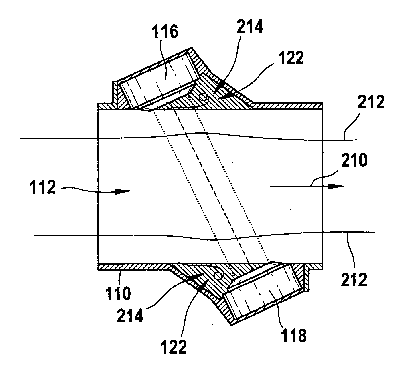
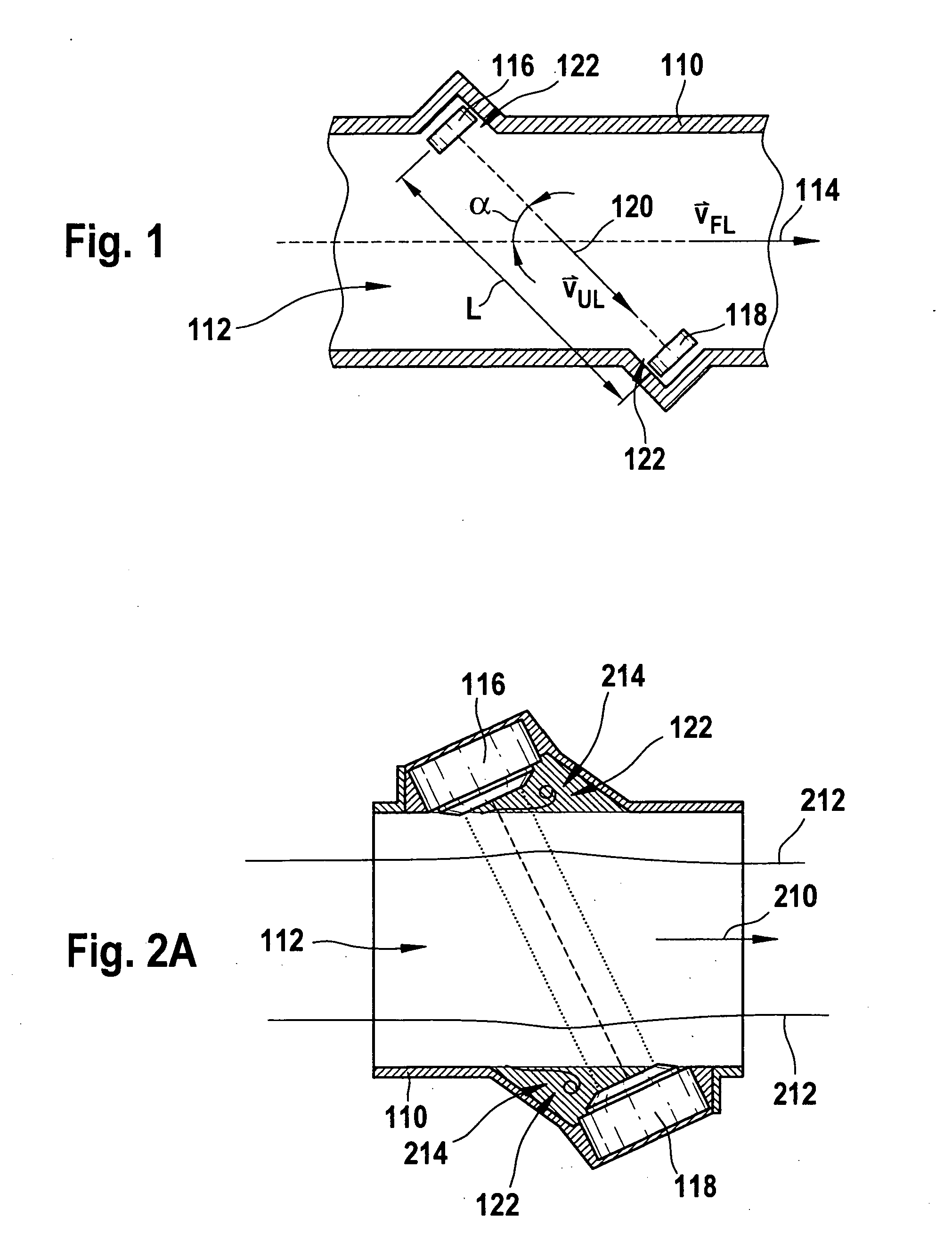
[0031] Similarly to FIG. 1, FIG. 2A shows an additional system having two diametrically opposed ultrasonic transducers 116, 118 which, in a direction transverse to primary flow direction 210 (i.e., parallel to flow velocity 114 in FIG. 1), are capable of exchanging ultrasonic waves at an angle to primary flow direction 210 which is different from 90°. As an example, FIG. 2A shows two flow lines 212 of the fluid. The flow of the fluid in the tube is predominantly free from separation areas.

[0032] The two ultrasonic transducers 116, 118 send signals to one another, the propagation times of which, as described above, allow a calculation of flow velocity vFL 114.

[0033] As shown in FIG. 2A, separation areas 214 are formed in the areas of the protrusions 122 upstrean of ultrasonic transducers 116 and 118, within which laminar flow no longer prevails, but a turbulent flow prevails instead. One result of these turbulences is that the simple equation (1) (see above) for calculating the sup...


PUM


Abstract

The measurement of volume flows or mass flows in the intake system of motor vehicle internal combustion engines plays a significant role in reducing pollutant emissions. Therefore, an ultrasonic flow meter for measuring a flow rate of a fluid flowing in a primary flow direction is described. The ultrasonic flow meter has at least two ultrasonic transducers, the ultrasonic transducers being capable of emitting and/or receiving ultrasonic waves at an angle α to the primary flow direction which is different from 90°. Furthermore, the ultrasonic flow meter has at least one guide element which is entirely or partially situated in the fluid. This guide element diverts at least one part of the flowing fluid in such a way that in the diversion, a velocity component is transferred to at least one part of the flowing fluid perpendicular to the primary flow direction. Guide vanes or displacers in particular are described as guide elements. In addition, turbulators may be provided on the guide elements, the turbulators generating a longitudinal fluid bed along the guide elements and thus causing the flow of the fluid to have a better contact with the guide elements when flowing around them. This reduces turbulences within the ultrasonic flow meter. Compared to the devices known from the related art, the ultrasonic flow meters described are distinguished by an improved signal-to-noise ratio and accordingly by a higher measuring precision.

Description

FIELD OF THE INVENTION [0001] Ultrasonic flow meters are used in the automotive industry, in particular in the intake system of internal combustion engines, for measuring volume flow or mass flow. Typically ultrasonic transducers are used which are capable of both emitting ultrasonic waves into a fluid and receiving ultrasonic waves. The propagation time of ultrasonic signals which are transmitted from an emitter to a receiver is influenced by the flow of the fluid. It is possible to infer the flow velocity of the fluid from the degree of influence of the propagation time. BACKGROUND INFORMATION [0002] British Published Patent Application No. 2 101 318 describes an ultrasonic flow meter in which two ultrasonic transducers are mounted on opposite sides of a pipe through which a fluid (112) flows. The transducers are situated slightly offset with respect to one another, so that ultrasonic waves emitted by one transducer and received by the second transducer propagate at an angle to th...

Claims


Application Information

Patent Timeline
Patent Type & Authority Applications(United States)
IPC IPC(8): G01F1/66
CPCG01F1/662G01F1/667G01F5/00
Inventor KONZELMANN, UWELANG, TOBIASGMELIN, CHRISTOPHRADWAN, SAMI
Owner ROBERT BOSCH GMBH
Why Eureka
Try Eureka