Bulk material pump feeder with reduced disk jamming
a technology of material pump feeder and disk jamming, which is applied in the direction of machines/engines, transportation and packaging, liquid fuel engines, etc., to achieve the effect of reducing the tendency of material jamming
- Summary
- Abstract
- Description
- Claims
- Application Information
AI Technical Summary
Benefits of technology
Problems solved by technology
Method used
Image
Examples
first embodiment
A. First Embodiment
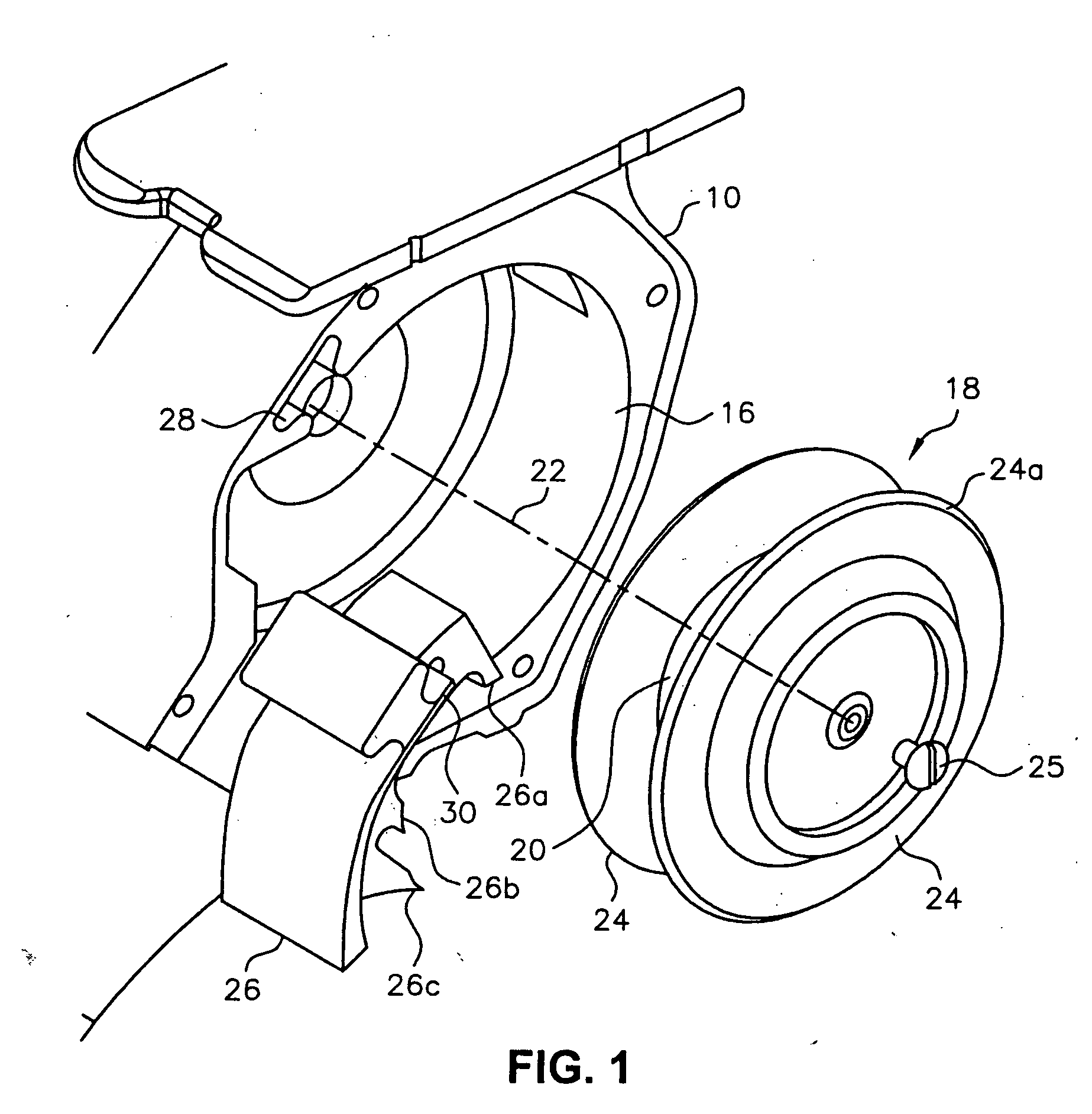
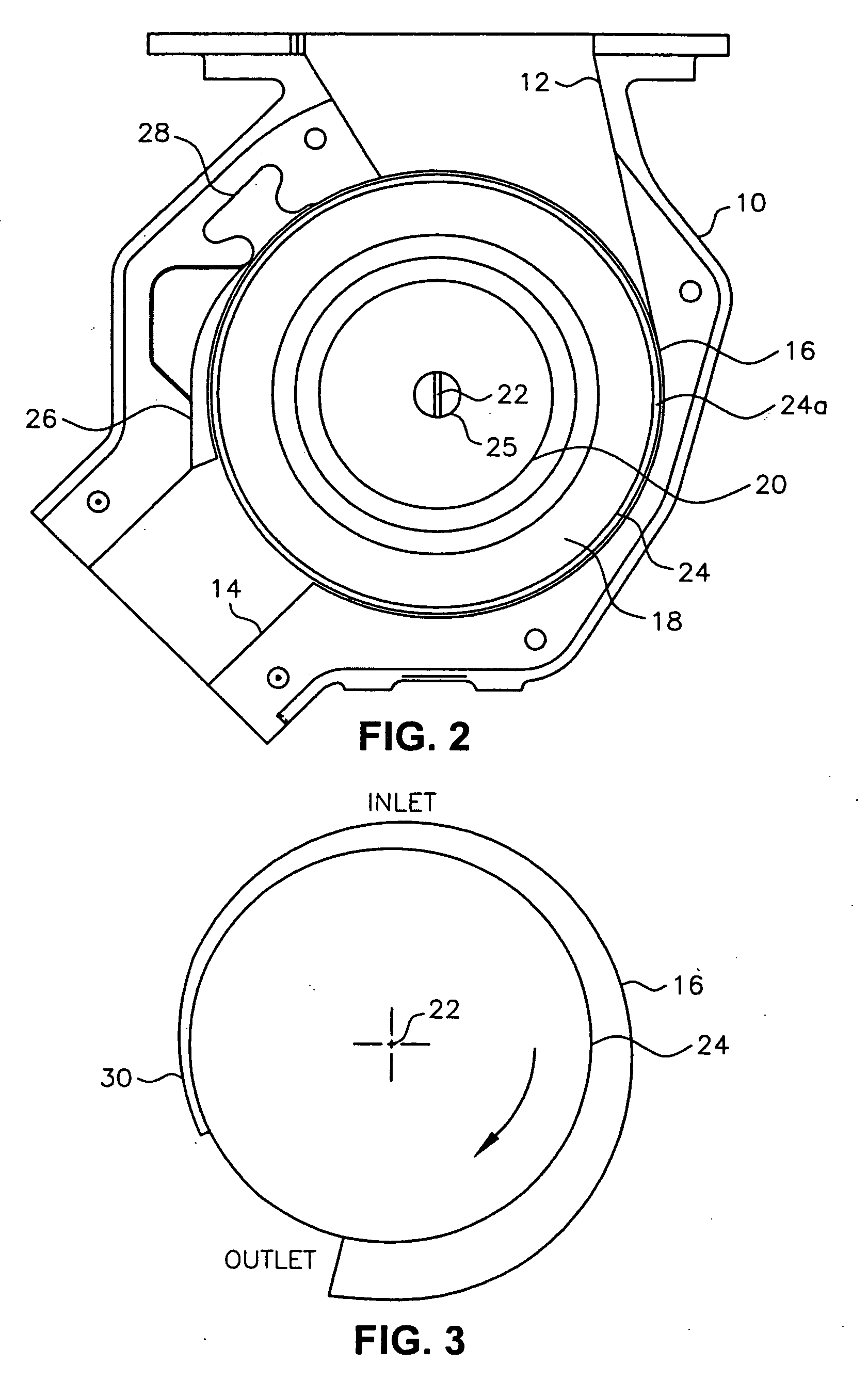
[0025] As shown most clearly in FIG. 3, which is a schematic drawing of the relationship between drive disks 24 and inner wall 16 of housing 10, the distance between the circumferential edges of drive disks 24 and inner wall 16 of housing 10 increases from Inlet 12 of housing 10 to OUTLET 14 of housing 10 in the direction of rotation of drive rotor 18, which is clockwise as indicated by the arrow for the embodiment of the invention illustrated in the figures and being described. Drive disks 24 and inner wall 16 of housing 10 can be shaped in different ways to provide the desired spacing between the two components. For the embodiment of the invention illustrated in the figures and being described, drive disks 24 are circular and extend away from hub 20 perpendicular to rotation axis 22 of hub 20, and inner wall 16 of housing 10 is spiral shaped. The spiral-shaped inner wall 16 of housing 10 can be defined by the Archimedes spiral equation:
R=θ*a
where: “R” is the ...
second embodiment
B. Second Embodiment
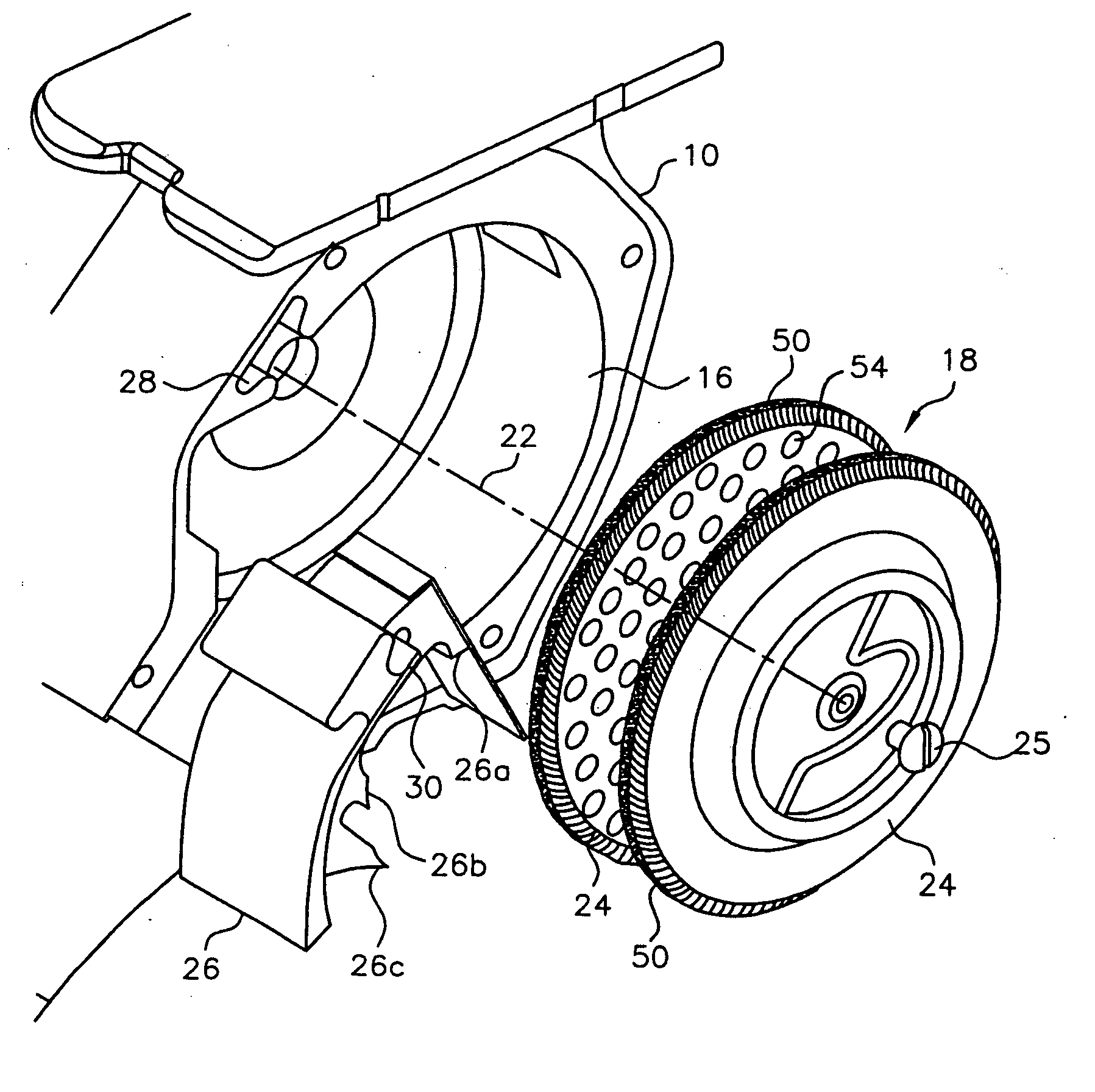
[0035] in the second embodiment of the present invention, as illustrated in FIGS. 6 and 7, a low-friction brush seal 50 is disposed on the periphery of drive disks 24. Brush seal 50 may be made of a number of different materials including, for example, pipe cleaner and rope. Brush seal 50 also may be constructed by combining a base made of metal, such as carbon steel, stainless steel, or aluminum, with a non-metallic brush made of a natural or synthetic fiber.
[0036] It is not necessary that brush seal 50 form a perfect seal between the periphery of drive disks 24 and inner wall 16 of housing 10. Although a small amount of contact occurs between brush seal 50 and inner wall 16 of housing 10, brush seal 50 induces little or no friction between drive disks 24 and inner wall 16 of housing 10 as drive disks 24 rotate. A low-friction seal is important to avoid an extra load on the drive motor. Moreover, the addition of brush seal 50 does not introduce tolerance issues...
third embodiment
C. Third Embodiment
[0043] In the third embodiment of the present invention, as illustrated in FIGS. 8 and 9, a third form of materials scraper 56 is provided. As illustrated in FIG. 8, materials scraper 56 may have a continuous scraping surface 40 like materials scraper 36 of FIG. 5. Alternatively, as illustrated in FIG. 9, materials scraper 56 may have a plurality of scraping tips 26a, 26b, and 26c as does materials scraper 26 shown in FIG. 4.
[0044] The function of materials scraper 56 is to scrape the materials handled by the bulk materials pump feeder from drive disks 24 and hub 20 as the materials exit the bulk materials pump feeder. For many materials, such scraping is unnecessary. Materials scraper 56 is especially adapted for those applications which require no or only a minimal amount of scraping. Specifically, relative to materials scraper 26 of FIG. 4 and materials scraper 36 of FIG. 5, a majority of the structure forming materials scraper 56 has been eliminated (shown be...
PUM
 Abstract
Description
Claims
Application Information
 - R&D
- Intellectual Property
- Life Sciences
- Materials
- Tech Scout
- Unparalleled Data Quality
- Higher Quality Content
- 60% Fewer Hallucinations
Browse by: Latest US Patents, China's latest patents, Technical Efficacy Thesaurus, Application Domain, Technology Topic, Popular Technical Reports.
© 2025 PatSnap. All rights reserved.Legal|Privacy policy|Modern Slavery Act Transparency Statement|Sitemap|About US| Contact US: help@patsnap.com


