In-line coating/sputtering system with internal static electricity/dust removal and recycle apparatuses

a technology of static electricity and recycling apparatus, which is applied in the field of coating/sputtering system, can solve the problems of unsatisfactory optical character, and affecting the quality of products, and achieve the effect of improving the cleanness of the transport process and reducing the occupied space of the recycle system

Inactive Publication Date: 2006-07-20
UVAT TECH
View PDF3 Cites 3 Cited by
  • Summary
  • Abstract
  • Description
  • Claims
  • Application Information

AI Technical Summary

Benefits of technology

[0008] The primary objective of the present invention is to provide an in-line coating / sputtering system with internal static electricity / dust removal and recycle apparatuses to improve the cleanness of the transport process and reduce the occupied space of the recycle system effectively.

Problems solved by technology

However, the quality highly demands on the cleanness of the transport process and the static electricity of the substrates.
If any suspension or dust adheres on the surface of substrates during the transport process, it will cause undesired optical character, unusual convexity or exceptional penetrability, and affect the quality of the products.
Moreover, if the substrates with the capacity of static electricity, not only the bonding force and uniformity of the coating / sputtering surfaces, but also the optical characteristics and electrical functions of the products are affected.
However, there are at least three serious problems for the conventional process.
Firstly, after the clean pre-treatment procedure in the external dust removal apparatus, the substrates and carrier are taken out of the apparatus, and wait for the coating / sputtering process.
The longer the waiting time, the more the amount of the pollution.
These drawbacks make the external clean pre-treatment fail to produce the expected effect.
On the other hand, the external static electricity removal apparatus faces the same problems.
Secondly, the conventional external cleanness procedure only removes the dust and static electricity on the top of the substrates and the carrier effectively, however, the dust and static electricity on the lateral side and bottom will still exist.
As a result, there still is some dust and static electricity on the substrates and carrier when they are delivered into the in-line coating / sputtering system.
It will affect the quality and yield of the products.
After a predetermined period, the suspension and dust will be deposited and adhere on the surface of the vacuum chambers, hence pollute the cleanness.
It will reduce the activation of system and the efficiency of production.
As a result, not only triple or more additional space will be occupied for the factory, but also the dust will adhere on the surface of the carrier and pollute again because the external recycle apparatus exposes in an open atmosphere environment, not in an isolated condition.

Method used


Image

  • In-line coating/sputtering system with internal static electricity/dust removal and recycle apparatuses
  • In-line coating/sputtering system with internal static electricity/dust removal and recycle apparatuses
  • In-line coating/sputtering system with internal static electricity/dust removal and recycle apparatuses

Examples


Embodiment Construction

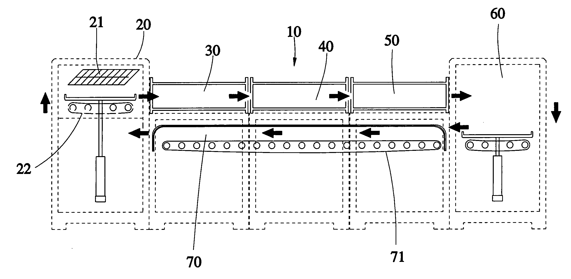
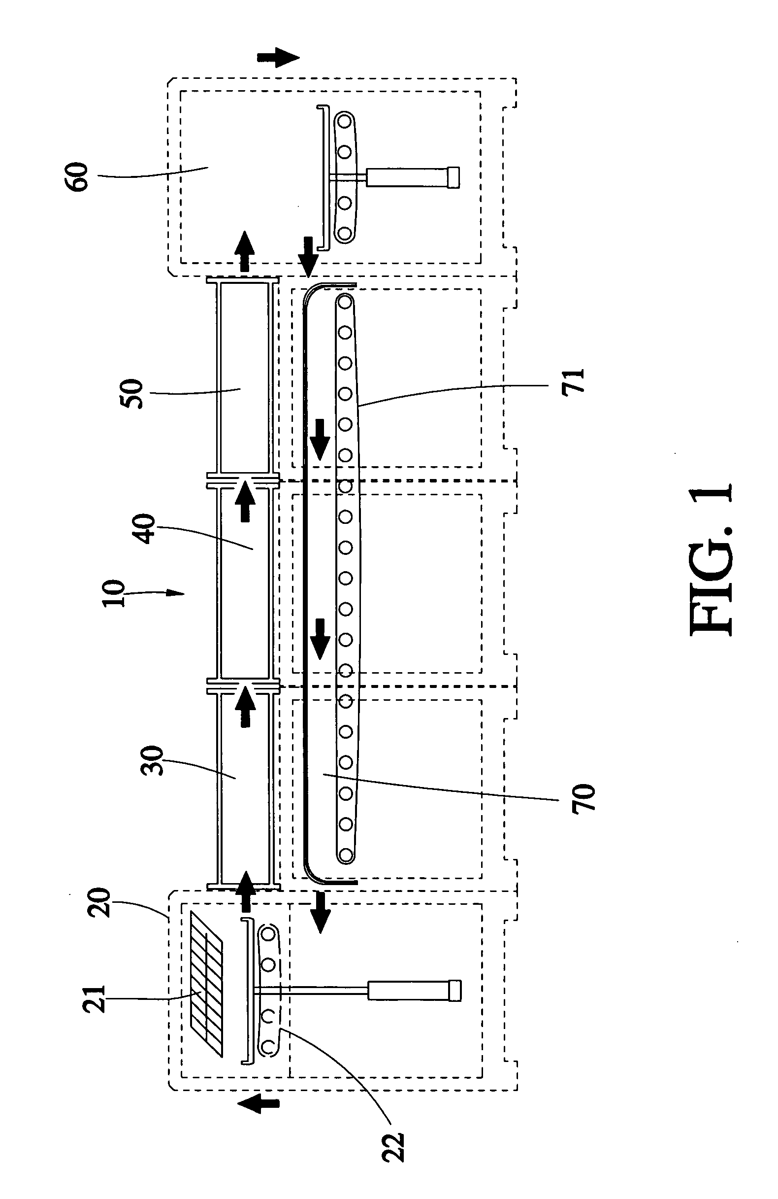
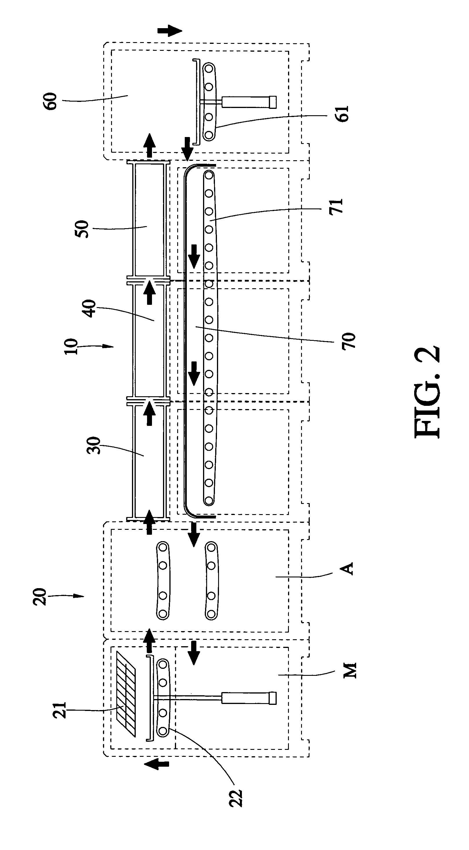
[0012] As shown in FIG. 1, an in-line coating / sputtering system 10 of the first preferred embodiment of the present invention comprises:

[0013] A clean region 20, which is integrated in the front of the in-line coating / sputtering system 10, is consisted of an internal static electricity / dust removal apparatus 21 and an elevator device 22.

[0014] A loading region 30, which is a pressure-down chamber with two gates on opposite ends thereof, is used to achieve an expected vacuum condition gradually, prior to the next coating / sputtering procedure. One of the gates is communicated with the chamber of the clean region 20.

[0015] A coating / sputtering region 40 has a vacuum chamber with two gates on opposite ends thereof, in which the coating / sputtering is accomplished. One of the gates is communicated with the pressure-down chamber of the loading region 30.

[0016] An unloading region 50, which is a pressure-up chamber with two gates on opposite ends thereof, is used to recover the atmosphe...


PUM

PropertyMeasurementUnit
pressureaaaaaaaaaa
bonding forceaaaaaaaaaa
vacuumaaaaaaaaaa

Abstract

An in-line coating/sputtering system includes a clean region with an internal static electricity/dust removal apparatus and an elevator device therein. A loading region has a pressure-down chamber with two gates on opposite ends thereof, one of which is communicated with the clean region. A coating/sputtering region has a vacuum chamber with two gates on opposite ends thereof, one of which is communicated with the pressure-down chamber of the loading region. An unloading region has a pressure-up chamber with two gates on opposite ends thereof, one of which is communicated with the vacuum chamber of the coating/sputtering region. A rear reversible region has an open chamber communicated with the pressure-up chamber of the unloading region, in which an elevator device is provided. A return region having a channel connecting the rear reversible region and the clean region, in which a backward transmission device is provided.

Description

BACKGROUND OF THE INVENTION [0001] 1. Field of the Invention [0002] The present invention relates generally to a coating / sputtering system, and more particularly to an in-line vacuum coating / sputtering system with internal static electricity / dust removal and recycle apparatuses. [0003] 2. Description of the Related Art [0004] The conventional in-line coating / sputtering system is consisted at least one loading chamber, one process chamber for reactive magnetron coating / sputtering, and one unloading chamber. The substrates usually are placed on a carrier for translation, and then delivered into the loading chamber. When the coating / sputtering process is finished, the products are taken out from the unloading chamber, and the carrier is returned to the loading chamber by way of the external recycle apparatus for the next batch. However, the quality highly demands on the cleanness of the transport process and the static electricity of the substrates. If any suspension or dust adheres on...

Claims


Application Information

Patent Timeline
Patent Type & Authority Applications(United States)
IPC IPC(8): C23C14/00
CPCC23C14/56C23C14/564
Inventor HUANG, TAI-YUANLIAO, HSUEH-CHIUNGYU, TUAN-JENLIU, CHUNG-CHUNGLEE, YUAN-CHISHEU, GEENG-JEN
Owner UVAT TECH
Why Eureka
Try Eureka