Method and device for determining the zero position of a yarn guide capable of cross-winding

a technology of cross-winding and yarn guide, which is applied in the direction of program control, ignition automatic control, instruments, etc., can solve the problems of yarn disadvantage, comparatively large control outlay, and high production cos

Inactive Publication Date: 2006-07-20
OERLIKON TEXTILE GMBH & CO KG
View PDF11 Cites 0 Cited by
  • Summary
  • Abstract
  • Description
  • Claims
  • Application Information

AI Technical Summary

Benefits of technology

[0022] Such a design of the mechanical drive elements assures that every movement of the step motor which relates to the cross-winding range, the cross-winding width or the cross-winding speed, is exactl...

Problems solved by technology

However, such yarn guide drums, which have proven themselves per se, are relatively expensive to produce and, because of the limits of the system, can only be used for producing cheeses of the “random cross-wound” type, since for producing a so-called “precision,” or “stepped precision winding,” the drive mechanism of the cheese and the drive mechanism of the-yarn cross-...

Method used


Image

  • Method and device for determining the zero position of a yarn guide capable of cross-winding
  • Method and device for determining the zero position of a yarn guide capable of cross-winding
  • Method and device for determining the zero position of a yarn guide capable of cross-winding

Examples


Embodiment Construction

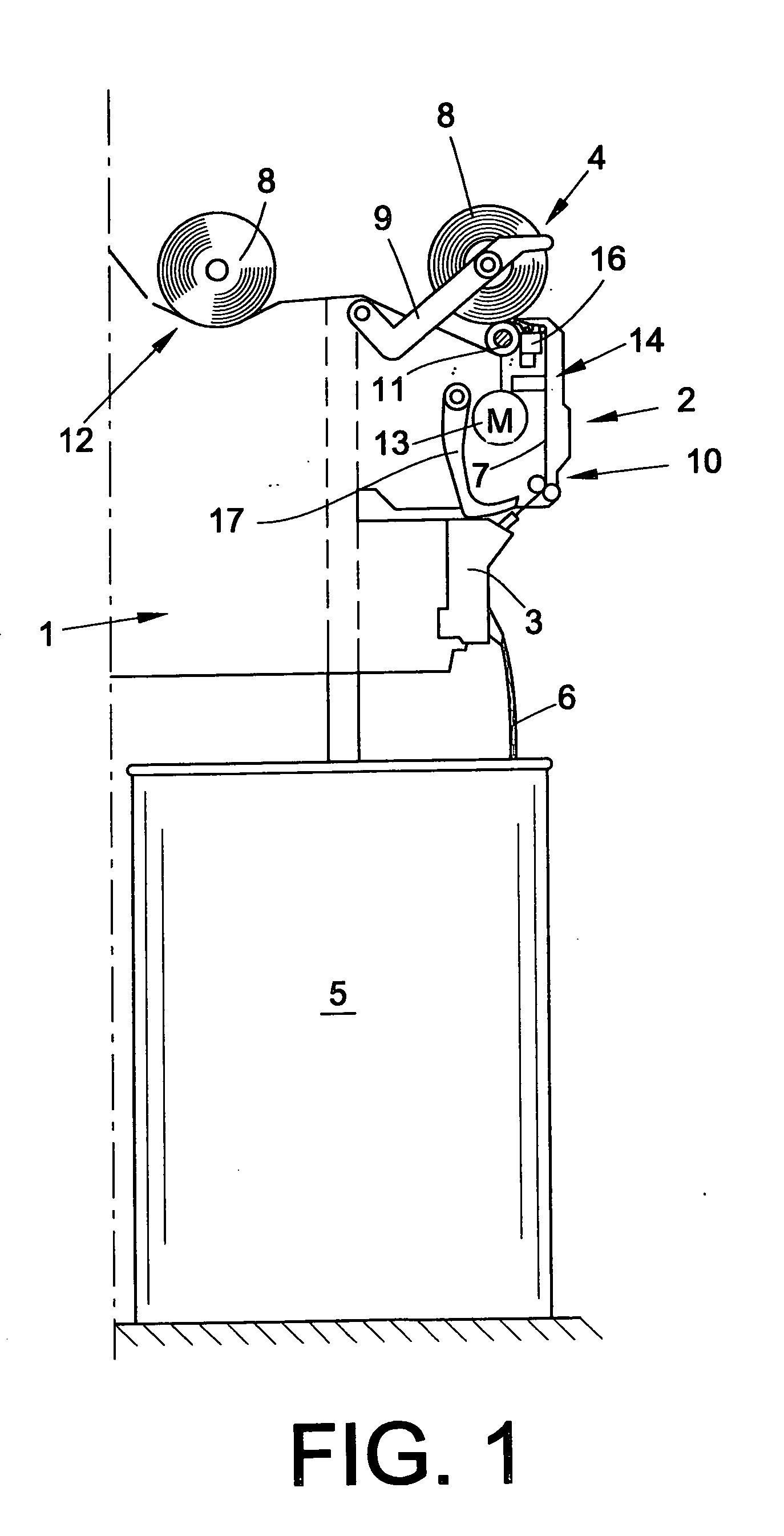
[0029] Referring now to the accompanying drawings, one side (i.e., one half) of a cheese-producing textile machine 1, in the exemplary embodiment an open-end rotor spinning machine, is schematically represented in a lateral end view in FIG. 1.

[0030] As known, such textile machines have multiple identical work stations 2 arranged side-by-side between their end frames (not represented). In this case, each of the work stations 2 has a spinning unit 3, as well as a bobbin-winding device 4. Slivers 6 stored in sliver cans 5 are processed into yarn 7 in the spinning units 3 and are subsequently wound into cheeses 8 on the bobbin-winding devices 4. The finished cheeses 8 are conveyed via a cheese transport installation 12 to a loading station (not represented) arranged at the machine.

[0031] As indicated in FIG. 1, the work stations 2 each have still further manipulating arrangements besides the spinning unit 3 and the bobbin-winding device 4, for example a yarn draw-off device 10, a suct...


PUM


Abstract

A system for determining a zero position of a yarn guide (25) of a textile winding device for cross-winding yarn into cheeses via a step motor (34). The yarn guide (25), acted upon by the step motor (34), is initially displaced in the direction of its zero position (NS) and positioned at a slow speed against a defined detent (15) downstream of the zero position (NS). Then, the step motor (34) is switched off, causing the rotor (41) of the step motor (34) to drop into one of two possible stop positions (RS1, RS2). Subsequently, the step motor (34) is switched on by an electrical current supply to its stator windings (20A, 20B) such that, when switched off, the rotor (41) of the step motor (34) is in the stop position (RS2) in which the yarn guide (25) is in its zero position (NS).

Description

CROSS-REFERENCES TO RELATED APPLICATIONS [0001] This application claims the benefit of German patent application DEP102005002409.2 filed Jan. 19, 2005, herein incorporated by reference. BACKGROUND OF THE INVENTION [0002] The present invention relates to a method and apparatus for determining a zero position of a yarn guide of a winding device of a textile machine producing cheeses, and relates more particularly to such a textile machine which is capable of cross-winding cheeses by means of a step motor. [0003] For producing a textile bobbin, it is known to be necessary, on the one hand, to put the respective textile bobbin into rotation and, on the other hand, to cross-wind the yarn running up on the bobbin along the bobbin axis. By means of a relatively rapid cross-winding of the yarn, it is possible to produce a so-called cross-wound textile bobbin, which is not only distinguished by a comparatively stable bobbin body, but also by good unwinding properties. [0004] In connection wi...

Claims


Application Information

Patent Timeline
IPC IPC(8): B65H54/28
CPCB65H54/2821B65H54/2833B65H54/2884B65H2701/31
Inventor SCHEER, GUNTEROEHRL, WILHELMPETERS, ERWINGEISLER, ROBERTSCHIFFERS, DIRKDOSS, GUDRUNPREUTENBORBECK, MAXIMILIAN
Owner OERLIKON TEXTILE GMBH & CO KG
Why Eureka
Try Eureka