High temperature resistant seal structure, valve comprising the same and aerospace craft side thruster

a technology of sealing structure and high temperature resistance, which is applied in the direction of valve housing, valve operating means/releasing devices, functional valve types, etc., can solve the problems of insufficient sealing, inability to use metal seals as usually used for sealing between stationary faces, and risk of actuator operation disorder, etc., to achieve high reliability and reduce mass

Inactive Publication Date: 2006-07-20
MITSUBISHI HEAVY IND LTD
View PDF16 Cites 0 Cited by
  • Summary
  • Abstract
  • Description
  • Claims
  • Application Information

AI Technical Summary

Benefits of technology

[0018] According to the third means of the present invention constructed as mentioned above, in the aerospace craft side thruster comprising the valve of the second means, even if the high temperature fluid of combustion gas, etc. is used as a working medium, the actuator of the thruster valve is prevented from being exposed to the high temperature environment caused by the leaking of the working medium. Thereby, an aerospace craft having a high reliability and reduced mass can be obtained.

Problems solved by technology

Conventionally, in the slidable portion between the valve casing 02 and the drive rod 07 of the thruster valve 01 as mentioned above, such a metal seal as usually used for sealing between stationary faces cannot be used, as the sealing is not sufficiently achieved because of the sliding motion of the sealing face.
For this reason, if a high temperature fluid, such as combustion gas, is used as the working medium a, the elastomer seal 010 often melts because of the heat transmitted from the drive rod 07 so that the combustion gas leaks to form a leak gas b. Thus, the actuator 08 is exposed to the high temperature environment by the leak gas b and there is caused a risk of operation disorder of the actuator 08.
Also, if a structure to protect the elastomer seal 010 and the actuator 08 is to be employed, the valve casing 02 has to be made larger by that extent and there is a problem that this leads to a larger size and mass increase of the side thruster device.
Thus, the drive force of the thruster valve 01 is inevitably made larger and there is caused a problem that this again leads to a larger size of the actuator 08.

Method used


Image

  • High temperature resistant seal structure, valve comprising the same and aerospace craft side thruster
  • High temperature resistant seal structure, valve comprising the same and aerospace craft side thruster
  • High temperature resistant seal structure, valve comprising the same and aerospace craft side thruster

Examples


Embodiment Construction

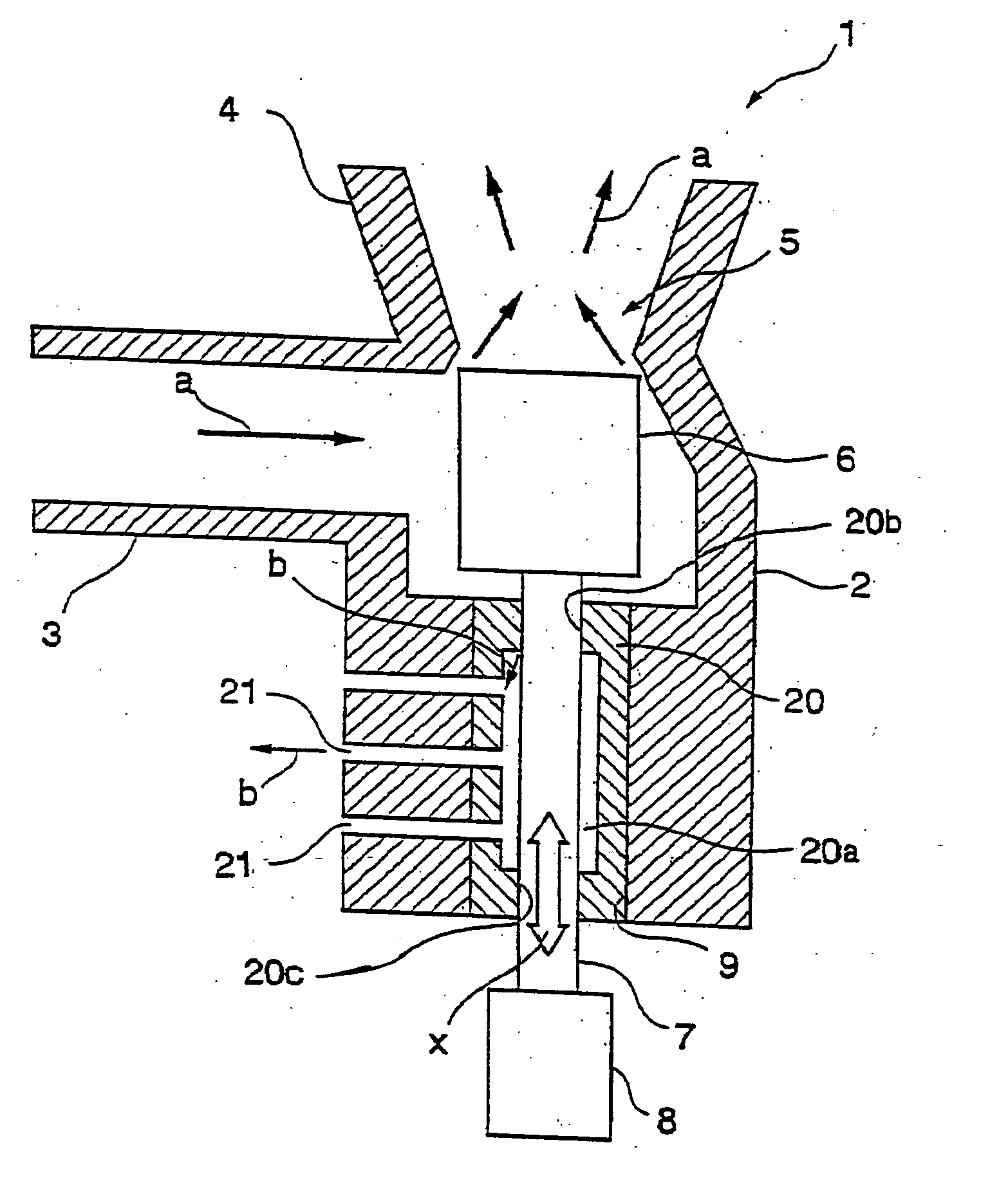
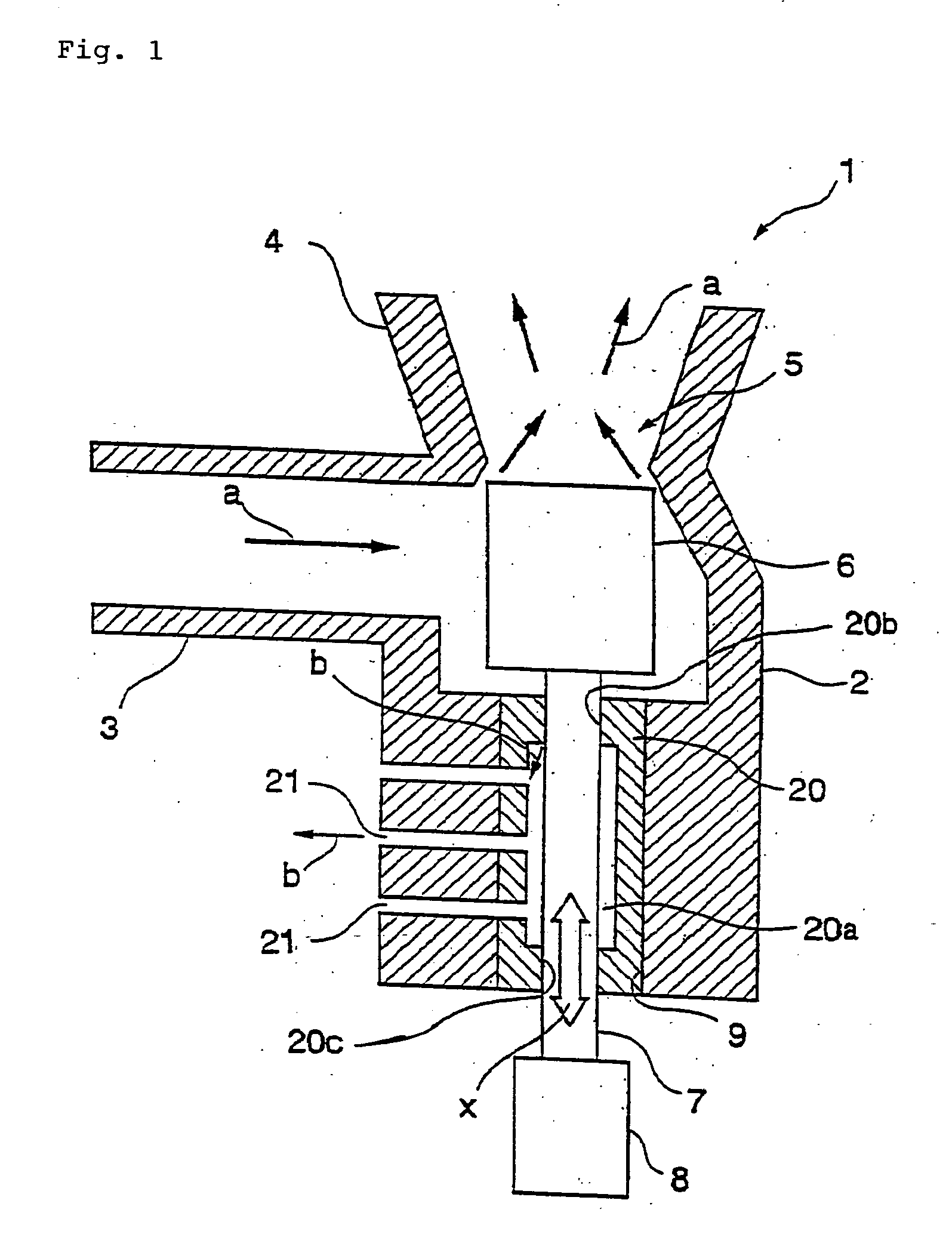
[0021] With reference to FIG. 1, a side thruster device for an aerospace craft or the like of one embodiment according to the present invention will be described. FIG. 1 is a longitudinal cross sectional view of a side thruster valve of the side thruster for an aerospace craft or the like of the present embodiment.

[0022] As shown in FIG. 1, a thruster valve 1 comprises a valve casing 2. The valve casing 2 comprises a supply port 3 through which working medium a of combustion gas or the like as a high temperature fluid is supplied and a nozzle 4 from which the working medium a is discharged. Within the valve casing 2, the supply port 3 and a nozzle throat portion 5 of the nozzle 4 communicate with each other.

[0023] Also, within the valve casing 2, a valve plug 6 opening and closing the nozzle throat portion 5 is arranged being connected to one end of a drive rod 7. The drive rod 7 passes through a drive rod through hole 9 of the valve casing 2 and the other end of the drive rod 7 p...


PUM


Abstract

A high temperature resistant seal structure having no problem that an actuator is exposed to a high temperature environment to lead to an operation disorder, a valve having a reduced valve drive force and an aerospace craft side thruster are provided. In a high temperature resistant seal structure, provided in a casing into which a high temperature fluid is supplied, comprising a shaft through hole portion into which a shaft to be driven in an axial direction of the shaft is inserted passing through the shaft through hole portion, a liner, made of graphite, comprising a cavity formed therein and slidable holes provided at both end portions of the cavity is provided being inserted into the shaft through hole portion so that the shaft slidably passes through the slidable holes with a seal state being maintained between the shaft and the liner and a relief hole is provided being bored in a lateral direction relative to the axial direction of the shaft so that the cavity and the outside of the casing communicate with each other. By this construction, leakage of the high temperature fluid in the shaft axial direction is prevented, the surrounding parts and components connected to a shaft end portion are prevented from being exposed to the high temperature fluid and a shaft drive force is reduced. Also, the valve and aerospace craft side thruster comprising the present seal structure can be made smaller and lighter and reliability thereof can be enhanced.

Description

TECHNICAL FIELD [0001] The present invention relates to a high temperature resistant seal structure of an axial directional slide shaft of a valve, etc. handling a high temperature fluid in a side thruster of an aerospace craft, etc. The present invention also relates to a valve comprising this seal structure as well as relates to a side thruster of an aerospace craft comprising this valve. BACKGROUND ART [0002]FIG. 2 is a longitudinal cross sectional view of a prior art side thruster valve used in an aerospace craft, etc. and description will be made based thereon. [0003] As shown in FIG. 2, a thruster valve 01 comprises a valve casing 02. The valve casing 02 comprises a supply port 03 through which working medium a is supplied and a nozzle 04 from which the working medium a is discharged. Within the valve casing 02, the supply port 03 and a nozzle throat portion 05 of the nozzle 04 communicate with each other. [0004] Also, within the valve casing 02, a valve plug 06 opening and cl...

Claims


Application Information

Patent Timeline
Patent Type & Authority Applications(United States)
IPC IPC(8): F16K31/44F42B10/66F16J15/00F16J15/16F16K27/02F16K41/00F16K41/04
CPCF16J15/004F16K27/02F16K41/04
Inventor HIDAKA, SHOZO
Owner MITSUBISHI HEAVY IND LTD
Why Eureka
Try Eureka