Motor driving control device to be driven at interval of constant time

a control device and constant time technology, applied in the direction of motor/generator/converter stoppers, motor/electric converter control, starter details, etc., can solve the problems of increasing the number of circuit components to be used, increasing manufacturing costs, and reducing switching operation efficiency. , to achieve the effect of reducing jarring noise and small loss

Active Publication Date: 2006-07-20
ALPS ALPINE CO LTD
View PDF4 Cites 16 Cited by
  • Summary
  • Abstract
  • Description
  • Claims
  • Application Information

AI Technical Summary

Benefits of technology

[0023] The invention has been finalized in view of the technical background, and it is an object of the invention to provide a motor driving control device which can use an FET serving as an element having a small loss and can reduce a jarring noise.

Problems solved by technology

Accordingly, the number of circuit components to be used is increased by that amount, and manufacturing costs tend to be increased.
However, a loss when the Darlington bipolar transistor is turned on is larger than a loss when the FET is turned on, and thus switching operation efficiency is slightly decreased.
Therefore, when the two bipolar transistors are turned on or off, a jarring noise may occur.

Method used


Image

  • Motor driving control device to be driven at interval of constant time
  • Motor driving control device to be driven at interval of constant time
  • Motor driving control device to be driven at interval of constant time

Examples


first embodiment

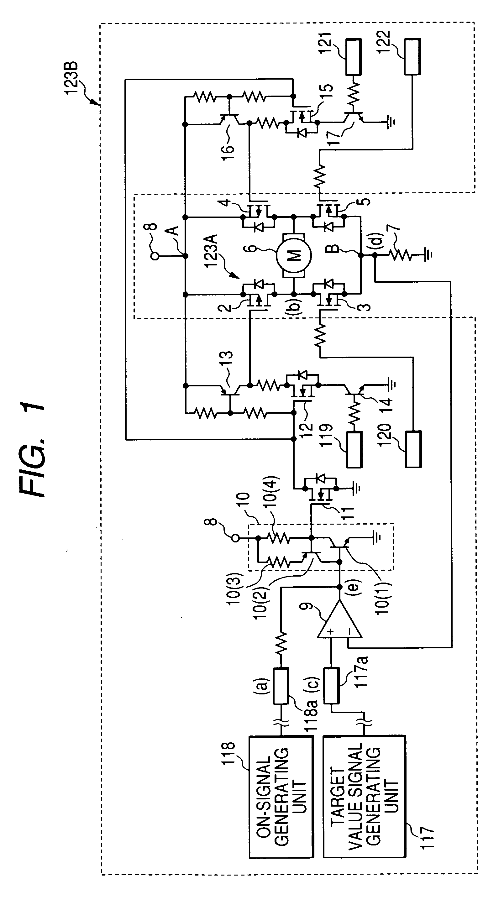
[0044]FIG. 1 is a circuit diagram showing the configuration of essential parts in a motor driving control device according to the invention.

[0045] As shown in FIG. 1, the motor driving control device according to the first embodiment uses a MOSFET as a switching element. The motor driving control device has a first pair of MOSFETs 2 and 3 that are connected in series between points A and B, a second pair of MOSFETs 4 and 5 that are connected in series between the points A and B, a direct-current motor 6 that is connected between a connection point of the first pair of MOSFETs 2 and 3 and a connection point of the second pair of MOSFETs 4 and 5, a current detection resistor 7 that is connected between the point B and a ground, and a power supply terminal 8 that is connected to the point A. These elements form an H-type bridge circuit. Besides, the motor driving control device according to the first embodiment has a comparator 9 having two input terminals and one output terminal, a ho...

second embodiment

[0060] Next, FIG. 3 is a circuit diagram showing the configuration of essential parts in a motor driving control device according to the invention. Moreover, in FIG. 3, the same parts as those in FIG. 1 are represented by the same reference numerals.

[0061] As shown in FIG. 3, a motor driving control device according to the second embodiment uses a MOSFET as a switching element, and has a MOSFET 2 that is connected in series between points A and B, together with a direct-current motor 6, a current detection resistor 7 that is connected between the point B and a ground, and a power supply terminal 8 that is connected to the point A. Besides, the motor driving control device according to the second embodiment has a comparator 9, a holding circuit 10 that has two transistors 10(1) and 10(2) to be brought into cross connection and two resistors 10(3) and 10(4), a MOSFET 11, a MOSFET 12 and a transistor 13 that drive the MOSFET 2, a target value signal generator 117, an on signal generato...

third embodiment

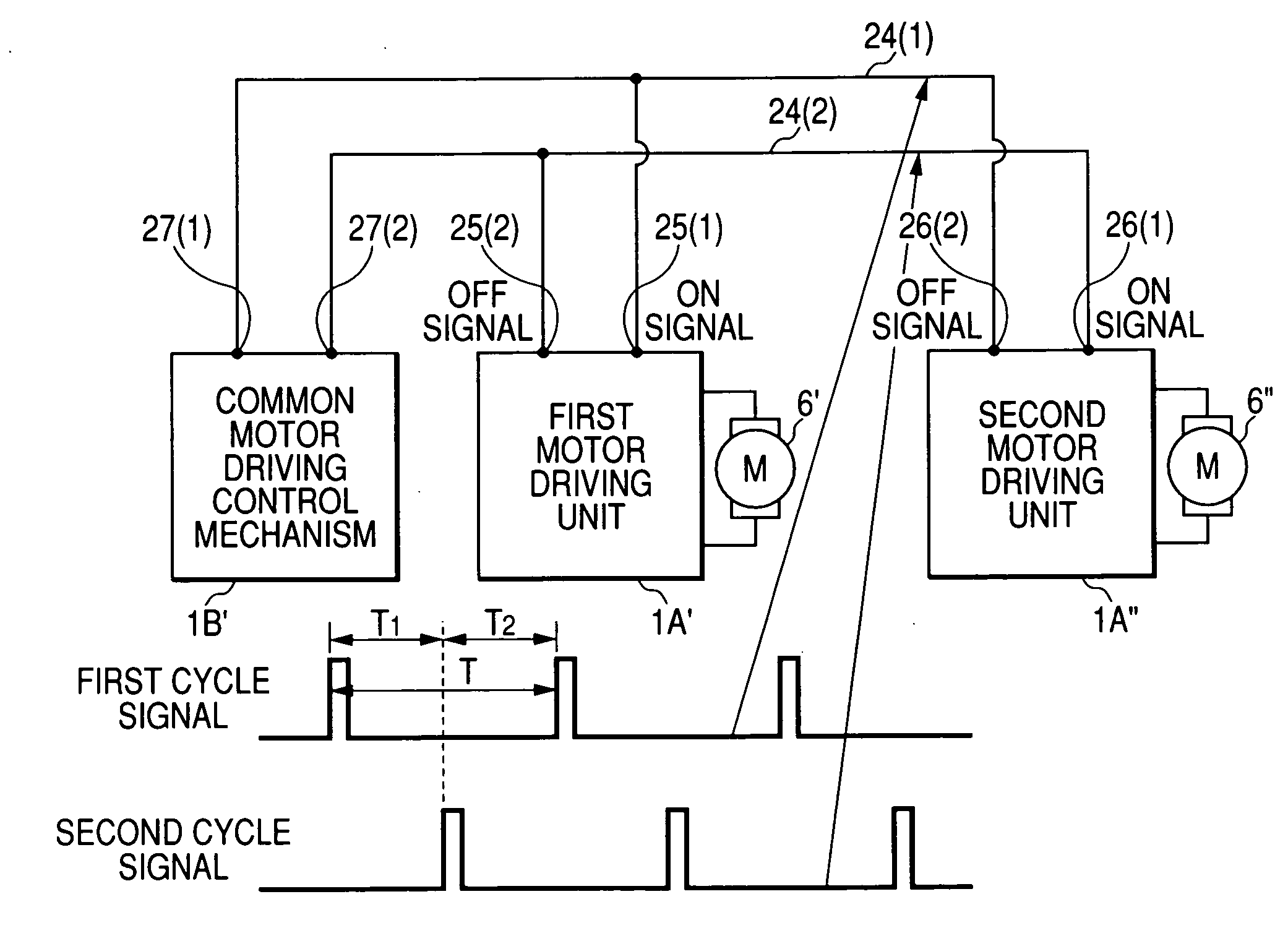
[0088] As such, according to the motor driving control device the motor 6 is driven when the first polarity change portion of the on signal to be supplied for each interval of predetermined time, and driving of the motor 6 stops at the earlier time from the time when the second polarity change portion of the off signal to be supplied for each interval of predetermined time and the time the average current value of the motor 6 reaches the target current value. Therefore, the average current value of the motor 6 can be maintained at the predetermined value, without making the change cycle of driving and non-driving of the motor 6 longer than the arrival interval of the first polarity change portion of the on signal. Further, the regenerative current of the motor 6 does not need to be accurately detected, and an unnecessary noise occurring at the time of the operation can be reduced.


PUM


Abstract

A motor driving control device includes a motor, a switch unit that controls driving of the motor, a current detection resistor that outputs a detection voltage indicating a current of the motor, a comparator that compares the detection voltage with a target current value, an on signal generating unit that generates an on signal, a polarity of which is changed for each interval of predetermined time, and a control unit that has the comparator, a holding circuit receiving the on signal to change a circuit state. When a change in polarity of the on signal is detected, the holding circuit holds the circuit state such that the switch unit is turned on and a current is supplied to the motor. When the comparator detects that the current of the motor is increased up to the target current value, the holding circuit holds the circuit state such that the switch unit is turned off.

Description

BACKGROUND OF THE INVENTION [0001] 1. Field of the Invention [0002] The present invention relates to a motor driving control device, and more particularly, to a motor driving control device which can be suitably used in an input apparatus with an operation feeling imparting function of imparting an operation feeling to a manual operating member connected to a rotational shaft of a motor. [0003] 2. Description of the Related Art [0004] In the related art, in a motor driving control device, which selectively rotates a direct-current motor in one direction or in a reverse direction, a bridge driving circuit, in which four switching elements are brought into H-type bridge connection, together with the direct-current motor, is used. In this case, the H-type bridge driving circuit is configured such that first and second switching elements are connected between a power supply and a reference potential point in series, third and fourth switching elements are connected between the power sup...

Claims


Application Information

Patent Timeline
Patent Type & Authority Applications(United States)
IPC IPC(8): H02P5/46
CPCH02P5/68H02P7/298
Inventor FURUKI, SHIGERU
Owner ALPS ALPINE CO LTD
Why Eureka
Try Eureka