
Selection of a mipmap level

a technology of mipmap and level, applied in the field of computer graphics processing, can solve the problems of high risk of choosing a too detailed level, too much memory bandwidth, and too coarse mipmap, so as to reduce the bandwidth of texture memory, reduce the effect of unnecessary high detail

Inactive Publication Date: 2006-07-20
KONINKLIJKE PHILIPS ELECTRONICS NV
View PDF6 Cites 15 Cited by
  • Summary
  • Abstract
  • Description
  • Claims
  • Application Information

AI Technical Summary

Benefits of technology

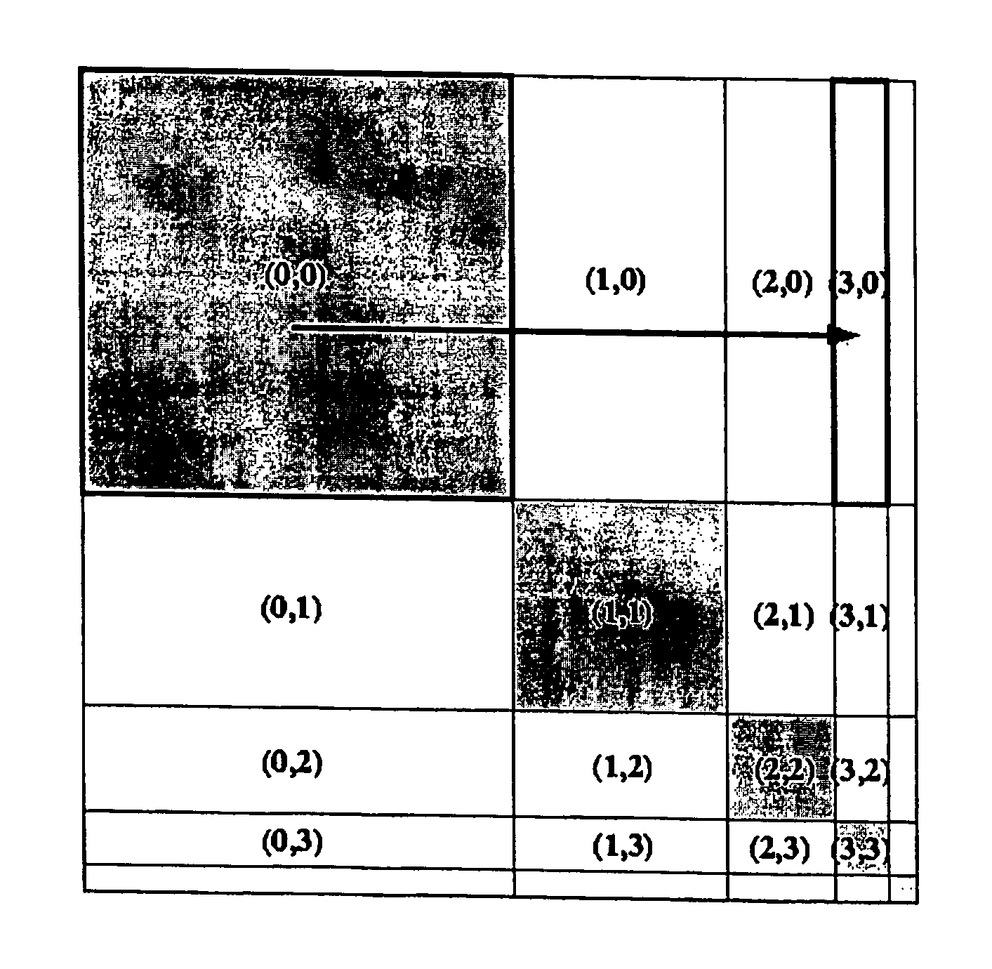
[0019] According the measures of the dependent claim 4, the texture memory stores a 4D mipmap structure. The texture space resampler operates on the 4D mipmap indicated by the finally determined levels (possibly with a lower resolution). The rasterizer still operates on the initial 4D mipmap (with possibly unnecessary high detail). The resampler provides the data to the rasterizer by reconstructing it from the finally identified 4D mipmap (e.g. through interpolation). In this way, bandwidth to the texture memory can be reduced at those texels where the quality does not suffer.
[0020] According the measures of the dependent claims 5, the texture memory stores a 3D mipmap structure, as is usually the case for computer graphics applications such as games. The texture space resampler generates the finally identified 4D mipmap on-the-fly from one of the 3D mipmaps. The non-prepublished European patent application IB02 / 05468 describes a method for generating a 4D mipmap on the fly from a 3D mipmap. This enables efficient high quality rendering also in combination with programs that do not supply a 4D mipmap to the graphics system.

Problems solved by technology

Choosing a too detailed mipmap generates too much memory bandwidth.
Choosing a too coarse mipmap generates an image of too low quality.
In particular, for a 2-pass forward texture mapping graphics system where the vertical mipmap level is fixed for the entire triangle on the basis of the maximum amount of detail required anywhere in the triangle, the risk of choosing a too detailed level is high.

Method used


Image

  • Selection of a mipmap level
  • Selection of a mipmap level
  • Selection of a mipmap level

Examples


Embodiment Construction

Overview of the System

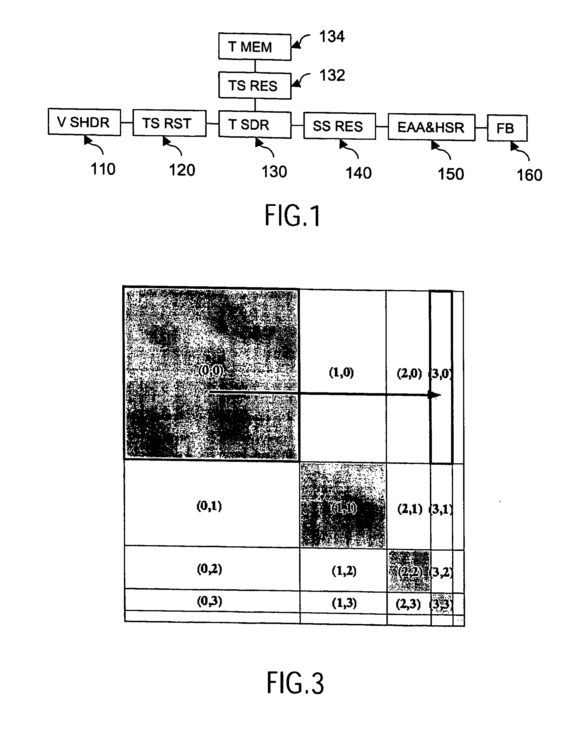
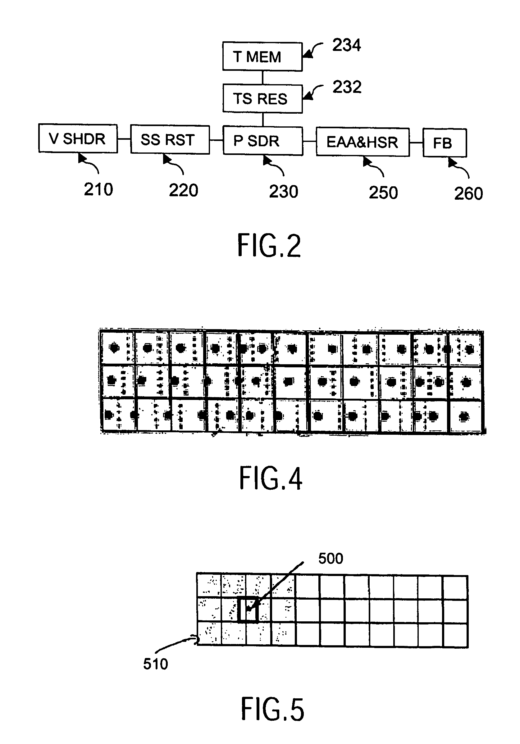
[0042]FIG. 1 shows an exemplary architecture of the last stages of a graphics pipeline in which the invention may be utilized. FIG. 1 shows a forward texture mapping system. FIG. 2 shows the last stages of a graphics pipeline of an inverse texture mapping system. In this description it is assumed that the models to be visualized are described using triangles as primitives. Persons skilled in the art can easily apply the same techniques to other primitives, such as other polygons or quads or curved surfaces such as Bezier patches. Input to the pipeline are primitives specified by its vertices by a graphics program, such as a computer game, and the earlier stages of the graphics pipeline. The primitives are given in the screen space, using (x, y) coordinates as well as the respective texel space, using (u, v) coordinates. The pipeline includes a vertex shader 110, texture space rasterizer 120, texel shader 130 with a texture space resampler 132 and texture memo...


PUM


Abstract

A computer graphics includes a texture memory (134) storing texture maps in a mipmap structure, texels in a texture map being specified by a pair of u and v coordinates. A rasterizer (120) determines for a texel (u, v) corresponding initial 4D mipmap levels (mmlu, mmlv) and a magnification factor representing a magnification that occurs when the texel is mapped to a corresponding pixel position on the display. It then determines final 4D mipmap levels in dependence on the determined initial 4D mipmap levels mmlu, mmlv, and the magnification factor. A texture space resampler (132) obtains texture data from a texture map identified by the pair off final 4D mipmap levels. A texture mapper (140) maps the obtained texture data to corresponding pixel data defining the display image.

Description

FIELD OF THE INVENTION [0001] The invention relates to a system and a method of computer graphics processing. BACKGROUND OF THE INVENTION [0002] An important element in rendering 3D graphics is texture mapping. Mapping textures onto surfaces of computer-generated objects is a technique which greatly improves the realism of their appearance. The texture is typically a 2D picture, such as a photograph or computer generated image. For example, (part of) a 2D image of a wall may be projected on a 3D representation of a wall in a computer game. Most 3D objects cover only a small part of the screen, often resulting in minification of the texture map (which is of sufficient resolution to also provide a reasonable appearance when viewed up close). Often, during texture mapping the 2D picture has to be minified considerably, for example if the wall is far removed. In principle, texture mapping could then be performed by significantly downscaling the original image. To reduce the bandwidth re...

Claims


Application Information

Patent Timeline
IPC IPC(8): G09G5/00G06T15/04
CPCG06T15/04
Inventor BARENBRUG, BART GERARD BERNARDMEINDS, KORNELIS
Owner KONINKLIJKE PHILIPS ELECTRONICS NV
Learn More