Liquid crystal display device

a liquid crystal display and display device technology, applied in the field of liquid crystal display devices, can solve the problems of difficult control reduced time required, and difficult to achieve ideal dark state in conventional tn (twisted nematic) mode, so as to improve response speed, suppress effect between liquid crystal molecules, and reduce the effect of after imag

Inactive Publication Date: 2006-07-20
SEMICON ENERGY LAB CO LTD
View PDF16 Cites 16 Cited by
  • Summary
  • Abstract
  • Description
  • Claims
  • Application Information

AI Technical Summary

Benefits of technology

[0021] Since a force which affects an orientation of liquid crystal molecules in a liquid crystal layer (frictional force or the like) can be controlled, response time (in particular, falling response time when an electric field is not applied) can be improved by performing the present invention.
[0022] Additionally, in the present invention, when a chemical compound having a liquid crystal skeleton is mixed in a liquid crystal layer, plural domain regions can be formed in the liquid crystal layer without disarraying an orientation of liquid crystal molecules included in the liquid crystal layer and an effect between liquid crystal molecules can be suppressed.
[0023] Thus, in the structure of the present invention, since a response speed improves, reduction of an after image can be improved and a display quality can be improved. Note that, since a response speed improves, the present invention can be used for a display method which is expected high speed operation such as a field sequential drive.

Problems solved by technology

However, conventional TN (Twisted Nematic) mode and the like were difficult to get an ideal dark state since it is affected by a slight phase difference that a liquid crystal represented.
This is because in the case of a TN mode, though a molecular major axis is shifted from a parallel state to a perpendicular state in an orientation state of liquid crystal molecules by means of applying an electric field, it is not easy particularly that a molecular in a place near to a substrate surface is shifted perpendicular to the substrate so that birefringence of liquid crystal in that portion remains.
Furthermore, in the case of a liquid crystal display device using nematic liquid crystal, a challenge is reducing time required for an operation of a liquid crystal molecule (hereinafter, response time) when a display signal is switched from one displaying state to the next displaying state.
However, in the case of display is made to a state of OFF from a state of ON (in the case of falling), control to improve response speed is difficult as compared to the case of rising since the OFF state can be obtained by returning liquid crystal molecules released from the control by the electric field to the orientation state before electric field has been applied.

Method used


Image

  • Liquid crystal display device
  • Liquid crystal display device
  • Liquid crystal display device

Examples


embodiment mode 1

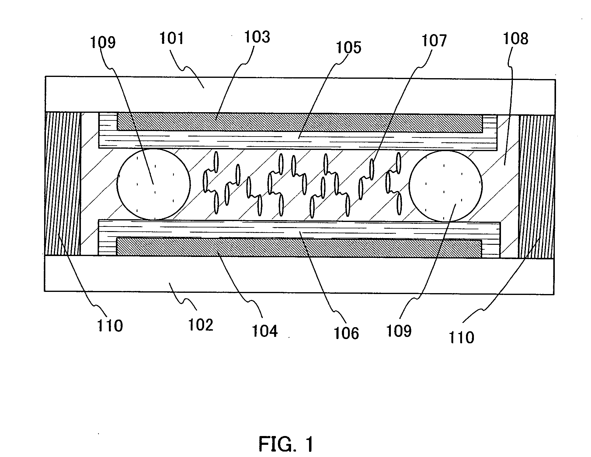
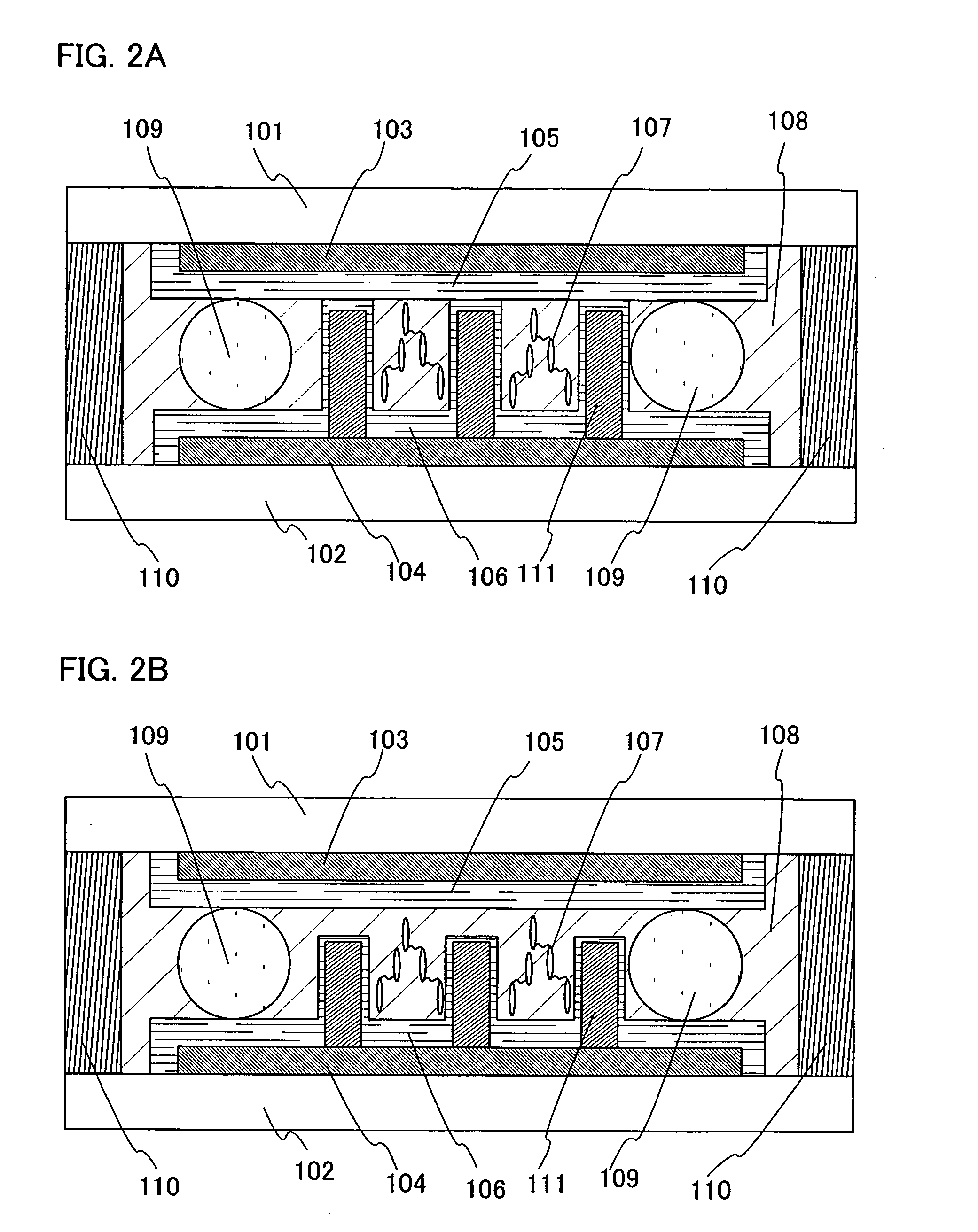
[0024] This embodiment mode explains a case in which a liquid crystal layer including liquid crystal molecules are divided into plural regions as a method for improving response speed of liquid crystal. FIG. 1 shows a cross section of a liquid crystal element in a liquid crystal display device of the present invention and shows one of embodiment modes of the present invention. Reference numerals 101 and 102 are substrates, 103 and 104 are electrodes, 105 and 106 are orientation films, 108 is a liquid crystal layer, 107 is a chemical compound having a liquid crystal skeleton, 109 is a spacer, and 110 is a sealing material.

[0025] The substrates 101 and 102 are materials which can transmit visible light and for example, glass, plastic, or quartz can be used. When optical modulation of a liquid crystal material is controlled by an electrical signal like the present invention, an electrode to be explained hereinafter and a dielectric film to insulate an electrode are arranged over a sur...

embodiment mode 2

[0044] Emobodiment mode 2 explained is a case in which a continuous pulse is applied to a liquid crystal display device as a method to improve response speed of liquid crystal. Note that, about constitution and a manufacturing method of a liquid crystal display device, FIG. 1 explained with Embodiment Mode 1 may be referred except that a liquid crystal layer is formed by only a liquid crystal material (a chemical compound having a liquid crystal skeleton is not included).

[0045] In other words, when electric field is applied or electric field is not applied, response speed of liquid crystal molecules can be improved since a constant oscillation is given to the liquid crystal molecules exisiting in the liquid crystal layer by applying a pulse to the liquid crystal display device repeatedly at regular time intervals. Note that, a pulse here is the voltage which is necessary that liquid crystal responds and it is necessary that a duty ratio of the pulse (a ratio of pulse application ti...

embodiment 1

[0046] In this embodiment, a liquid crystal element including a chemical compound having a liquid crystal skeleton in a liquid crystal layer is formed as described in Embodiment Mode 1 and a result of evaluating an optical property thereof is described.

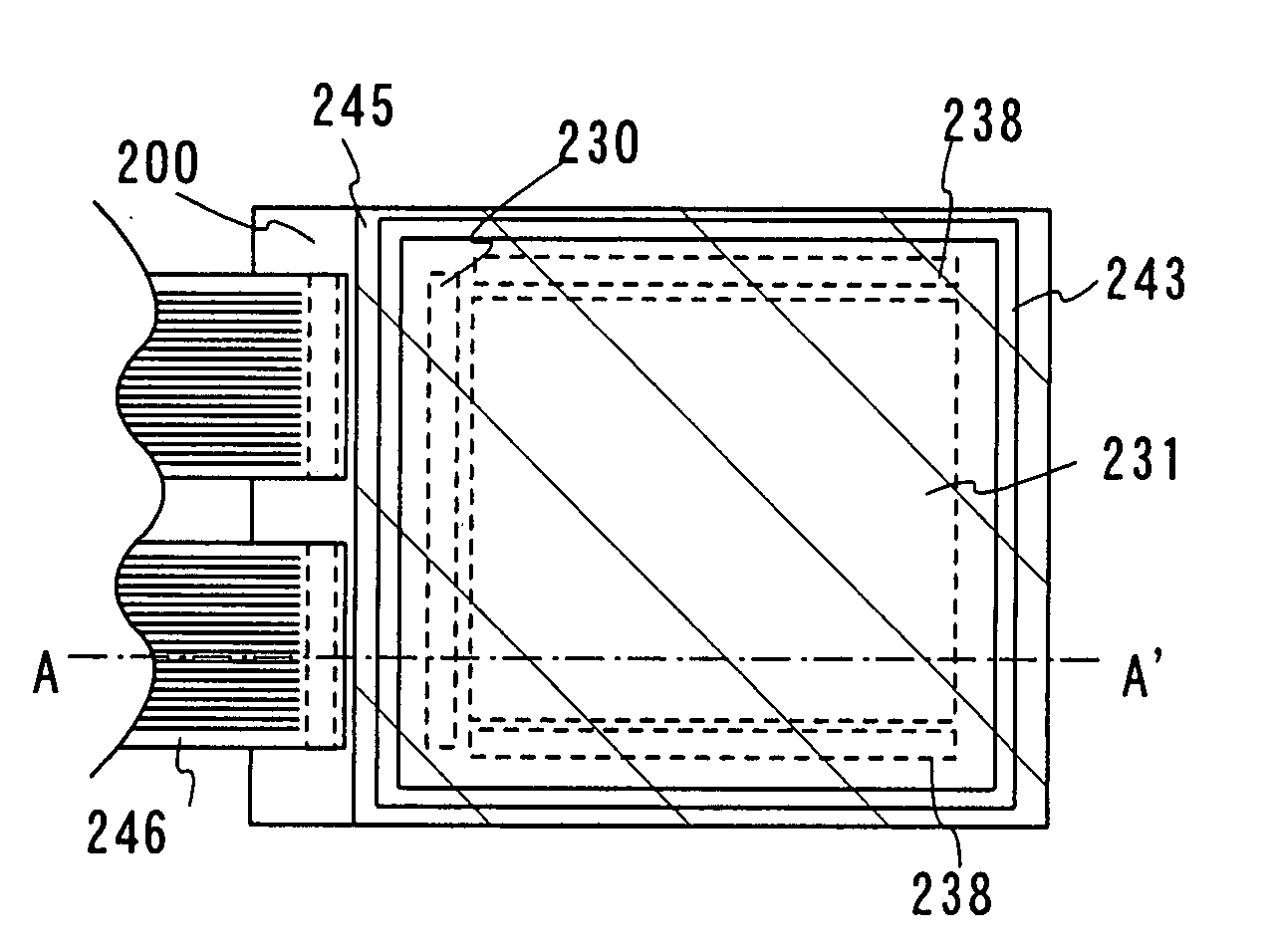
[0047] Manufacturing of a liquid crystal element in this embodiment, a glass substrate that thickness was 0.7 mm and outline is 2 cm×2 cm is used. On the upper side of this glass substrate, an indium tin oxide film was formed as a transparent electrode. The indium tin oxide film was used in an electrode part formed of 7 mm×7 mm form for driving liquid crystal and in an extraction electrode part for applying electric field to liquid crystal from outside. An orientation film for perpendicular orientation (SE1211 produced by Nissan Chemical Industries) was used as an orientation film to orientate a liquid crystal material. A thin film of the perpendicular orientation film was formed on the upper side of the substrate and the film thickn...


PUM

PropertyMeasurementUnit
thicknessaaaaaaaaaa
thicknessaaaaaaaaaa
thicknessaaaaaaaaaa

Abstract

[Problem]In the present invention, it is an object to improve display quality by improving response speed of a liquid crystal element in a liquid crystal display device, in particular, response speed in the case of falling. [Means for Solving the Problems]In the present invention, it is characterized that a liquid crystal layer is divided into plural regions (domains) substantially by mixing a chemical compound including a liquid crystal skeleton in a liquid crystal layer exisiting liquid crystal molecules as a technique to improve response speed of a liquid crystal element in a liquid crystal display device for solving the above problem.

Description

TECHNICAL FIELD [0001] The present invention relates to a technique for improving a response speed of a display device (including a liquid crystal element) applying a liquid crystal. BACKGROUND ART [0002] A display device applying a liquid crystal material is used extensively as a light-weight and thin display device. The liquid crystal display device interposes a liquid crystal material between two pieces of flat plates such as glass substrates. By applying an electric field by at least one electrode arranged on a flat surface where the liquid crystal of a flat plate is arranged, a liquid crystal molecule is switched by the intensity and existence or nonexistence of the electric field. Since optical property of the liquid crystal is changed in conjuction with it, displaying of an image or the like is performed using this change of optical property. [0003] A nematic liquid crystal is generally used as a liquid crystal material used for a liquid crystal element. A nematic liquid crys...

Claims


Application Information

Patent Timeline
Patent Type & Authority Applications(United States)
IPC IPC(8): G02F1/1335
CPCG02F1/0045G02F1/133377Y10T428/1005Y10T428/10Y10T428/1036C09K2323/03C09K2323/02C09K2323/00
Inventor NISHI, TAKESHIISHITANI, TETSUJIKUBOTA, DAISUKE
Owner SEMICON ENERGY LAB CO LTD
Why Eureka
Try Eureka