Optical fiber

a technology of optical fiber and holey fiber, which is applied in the field of holey fiber, can solve the problems of high manufacturing cost of holey fiber, difficult to put holey fibers to practical use in the signal light wavelength range, and low transmission loss of holey fiber

Inactive Publication Date: 2006-07-20
SUMITOMO ELECTRIC IND LTD
View PDF3 Cites 8 Cited by
  • Summary
  • Abstract
  • Description
  • Claims
  • Application Information

AI Technical Summary

Benefits of technology

[0011] On the other hand, the standard optical fiber having a solid configuration usually has a negative chromatic dispersion (normal dispersion) in the wavelength range smaller than a wavelength of 1.3 μm in the near-infrared region. In general, in order to develop nonlinear phenomena, it is preferable that the chromatic dispersion is close to zero dispersion, and therefore it is necessary that the fiber characteristics are adjusted such that the chroma

Problems solved by technology

The inventors have studied the conventional holey fibers in detail, and as a result, have found problems as follows.
However, the holey fiber has a transmission loss of about 10 dB/km, which is greater by substantially one order of magnitude than those of highly-nonlinear optical fibers having a solid configuration.
Another problem is that the manufacturing costs of holey fibers are high.
For these reasons, it has been difficult to put holey fibers to practical use in the signal light wave

Method used


Image

  • Optical fiber
  • Optical fiber
  • Optical fiber

Examples


first embodiment

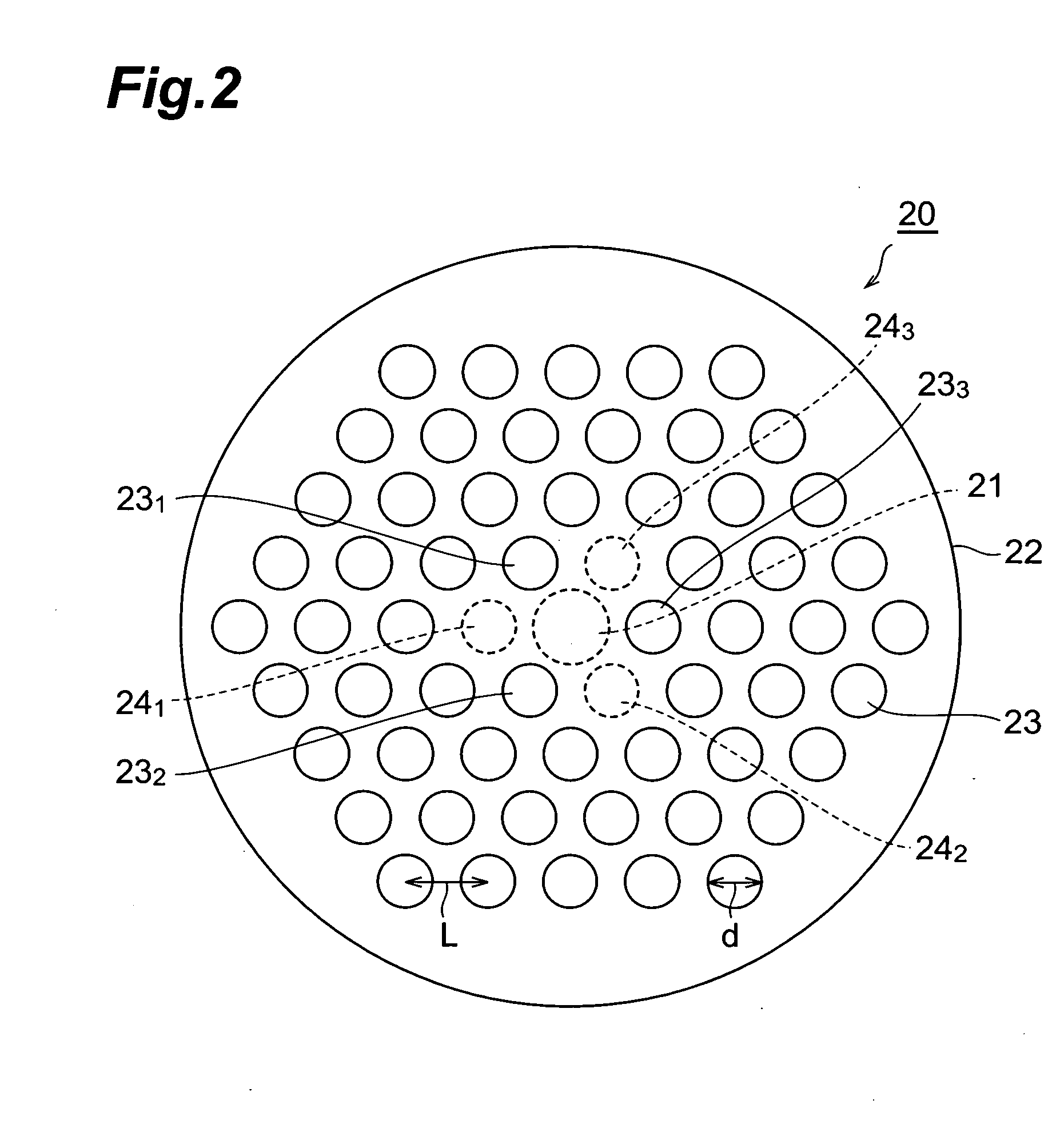
[0037] First, a first embodiment of an optical fiber according to the present invention will be described. FIG. 2 is a view illustrating the cross-sectional configuration of the optical fiber according to the first embodiment of the present invention. There is illustrated, in FIG. 2, the placement of plural holes 23 in a cross section orthogonal to the longitudinal direction of the optical fiber 20 according to the first embodiment.

[0038] The optical fiber 20 according to the first embodiment comprises a solid core region 21 extending along the longitudinal direction of the fiber 20 (the direction perpendicular to the paper face) and a cladding region 22 provided around the outer periphery of the core region 21, wherein there are provided, in the cladding region 22, with the plural holes 23 having a round-shaped cross-section and extending along the longitudinal direction. The portion of the cladding region 22 other than the holes 23 and the core region 21 are constituted of silica...

second embodiment

[0045] First, a second embodiment of an optical fiber according to the present invention will be described. FIG. 3 is a view illustrating a cross-sectional configuration of the optical fiber according to the second embodiment of the present invention. There is similarly illustrated, in FIG. 3, the placement of plural holes 33 in a cross-section orthogonal to the longitudinal direction of the optical fiber 30.

[0046] The optical fiber 30 according to the second embodiment illustrated in FIG. 3 comprises a solid core region 31 extending along the longitudinal direction of the fiber 30 (the direction perpendicular to the paper) and a cladding region 32 provided around the outer periphery of the core region 31, wherein there are provided, in the cladding region 32, with the plural holes 33 having a round-shaped cross-section and extending along the longitudinal direction. The portion of the cladding region 32 other than the holes 33 and the core region 31 are comprised of silica glass a...

modified embodiment

[0053] In the optical fiber 20 according to the first embodiment having the aforementioned configuration (FIG. 2), the holes 23 constituting the first layer closest to the core region 21 are placed such that the arrangement thereof has three-fold rotational symmetry about the core region 21. Further, the holes 23 constituting the respective remaining layers are placed such that the arrangement thereof has six-fold rotational symmetry about the core region 21. On the other hand, in the optical fiber 30 according to the second embodiment (FIG. 3), the holes 33 constituting the first and second layers positioned in order from the core region 31 are placed such that the arrangement thereof has three-fold rotational symmetry about the core region 31. The holes 33 constituting the remaining third and fourth layers are placed such that the arrangement thereof has six-fold rotational symmetry about the core region 31. Here, it is preferable that the center of the hole arrangement correspond...


PUM

PropertyMeasurementUnit
Lengthaaaaaaaaaa
Lengthaaaaaaaaaa
Lengthaaaaaaaaaa

Abstract

The present invention relates to an optical fiber having a configuration which enables utilization of nonlinear phenomena in the near-infrared region. The optical fiber is directed to a holey fiber having a core region extending along a predetermined axis and a cladding region with plural holes arranged along the core region. The plural holes are arranged to constitute plural layers about the core region in the cross-section orthogonal to the predetermined axis. The three holes constituting the first layer (the innermost layer) closest to the core region correspond to three vertexes from among the six vertexes of a regular hexagon and are placed such that the arrangement of the three holes has three-fold rotational symmetry. The optical fiber enables utilization of nonlinear phenomena in the near-infrared region, by properly adjusting the hole diameter d and the pitch L between adjacent holes from among the holes constituting a single layer.

Description

BACKGROUND OF THE INVENTION [0001] 1. Field of the Invention [0002] The present invention relates to a so-called holey fiber comprising a solid core region and a cladding region in which plural holes extending along the core region are provided. [0003] 2. Related Background Art [0004] A so-called holey fiber comprises a solid core region extending along a longitudinal direction of the fiber and a cladding region in which plural holes, extending along the core region while surrounding the core region, are provided. FIG. 1 is a view illustrating the cross-sectional configuration of a conventional holey fiber 10. There is illustrated, in FIG. 1, the arrangement of the plural holes 13 in a cross section orthogonal to the longitudinal direction of the holey fiber 10. In FIG. 1, circles illustrated by a solid line in the cladding region 12 represent holes 13. On the other hand, circles illustrated by a dot line do not represent holes, but represent regions or positions (the same applies t...

Claims


Application Information

Patent Timeline
IPC IPC(8): G02B6/032
CPCC03B37/0122C03B2203/14C03B2203/19C03B2203/20C03B2203/42G02B6/02214G02B6/02338G02B6/02347G02B6/02357G02B6/02361G02B6/105
Inventor SAITO, TATSUHIKOTAKAHASHI, KENICHIROKATAYAMA, TETSUTAROU
Owner SUMITOMO ELECTRIC IND LTD
Why Eureka
Try Eureka