Shaft tool and associated coolant/lubricant feeding point

a technology of shaft tool and feeding point, which is applied in the direction of boring/drilling equipment, turning equipment, maintenance and safety accessories, etc., can solve the problems of increasing tool costs, inability to reliably ensure, and considerable damage, and achieves the effect of convenient manufacturing

Active Publication Date: 2006-07-20
GUEHRING JOERG
View PDF17 Cites 8 Cited by
  • Summary
  • Abstract
  • Description
  • Claims
  • Application Information

AI Technical Summary

Benefits of technology

[0013] It is thus the object of the invention to create a shaft tool of the type described in the introduction, which tool is easier to manufacture and which can nevertheless form part of an effective interface for the coolant / lubricant feed into a tool. It is a further object of the invention to provide coolant / lubricant transfer for such a tool, wherein a configuration that can be produced economically ensures that the coolant / lubricant is fed through an insert and into the corresponding internal duct in the tool, of which duct there is at least one, with such infeed, to the greatest extent possible, being free of any significant loss of pressure, and with said coolant / lubricant thus being fed to the cutter at homogeneous quality.

Problems solved by technology

Any fluctuations in quality, for example fluctuations caused by cyclical or spontaneous demixing in the aerosol that is supplied at pressure, can result in unforeseeable tool breakage, and consequently, as a result of interruption of the production, to considerable damage.
It has been shown that this design cannot reliably ensure that the desired cooling or lubricating effect occurs in a satisfactory manner, in particular if the tool is operated using so-called minimal quantity lubrication.
However, this known solution requires a comparatively complex geometry of the engaging connecting surfaces between the tool shaft and the feed part, as a result of which tool costs increase, all the more so since the tools are frequently made from particularly high-strength materials that are more difficult to machine.

Method used


Image

  • Shaft tool and associated coolant/lubricant feeding point
  • Shaft tool and associated coolant/lubricant feeding point
  • Shaft tool and associated coolant/lubricant feeding point

Examples


Embodiment Construction

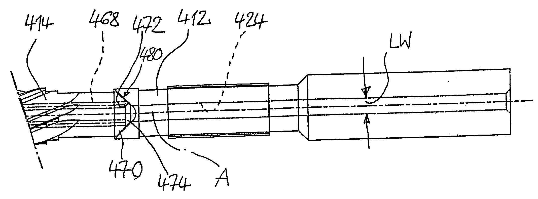
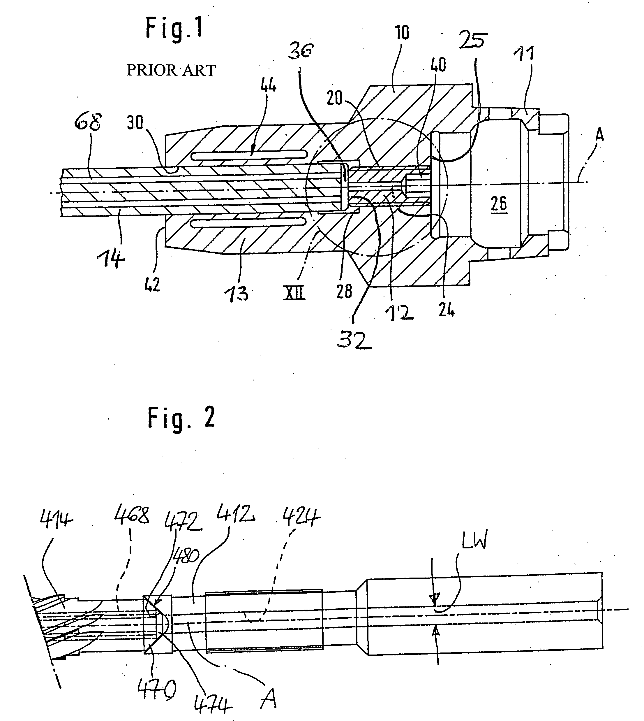
[0038] An embodiment of the invention, which embodiment is shown in FIG. 2, shows a design according to the invention of a shaft tool which advantageously can be used with a specially designed minimal-quantity-lubrication feed interface, which is shown by means of a connection between a first tool shaft part 412 and a second shaft part 414 which forms or carries the cutting part.

[0039] Feed-in of coolant / lubricant takes place from a central duct 424, arranged in the first shaft part 412, into eccentrically arranged internal coolant ducts 468 of the second shaft part 414. Two coolant ducts are provided that extend in a straight line in axial direction, which coolant ducts are situated on a common graduated circle so as to be diametrically offset from each other. However, it should already be pointed out at this stage that the coolant-lubricant infeed that will be described in more detail below is not limited to a particular type and design of the internal coolant ducts, which for ex...


PUM

PropertyMeasurementUnit
diameteraaaaaaaaaa
widthaaaaaaaaaa
inner widthaaaaaaaaaa

Abstract

A shaft tool with a machining section and a cylindrical shaft which comprises at least one internal coolant/lubricant duct which on its end facing away from the machining section comprises at least one orifice, wherein the shaft forms a conical fitting surface that encloses the orifice. A device comprising a shaft tool and a connection piece, the connection piece comprising a centric coolant/lubricant supply duct which exits in an apex region of an inner cone which accommodates in a positive-locking manner the conical fitting surface of the shaft tool, the conical fitting surface facing the inner cone.

Description

[0001] This application is a Continuation of International Application PCT / EP2004 / 011576, filed Oct. 14, 2004, the entirety of which is incorporated herein by reference. This application claims the benefit of German Application No. DE 103 47 755.1, filed Oct. 14, 2003.FIELD OF THE INVENTION [0002] The invention generally relates to the design of a shaft tool, such as e.g. a drilling, milling, reaming, thread-forming or thread cutting tool, that comprises an internal coolant duct and is characterized in that while being economical to produce it is in a particularly effective way suitable for supplying the cutters with coolant / lubricant. BACKGROUND OF THE INVENTION [0003] As a rule, shaft tools of this type are supplied with coolant / lubricant to a coolant / lubricant feeding point, for example in the form of a connection piece comprising a central coolant / lubricant supply duct. Frequently, connection to a supply part of a minimal-quantity-lubrication system takes place within a chuck. [...

Claims


Application Information

Patent Timeline
Patent Type & Authority Applications(United States)
IPC IPC(8): B23B51/06B23D77/00B23Q11/10
CPCB23B51/06B23B2231/0204B23B2251/02Y10T408/907B23Q11/1023Y10T408/45Y10T408/44B23B2265/08B23Q11/10
Inventor HAENLE, PETERGSAENGER, DIETER
Owner GUEHRING JOERG
Why Eureka
Try Eureka