VSAT block up converter (BUC) chip

a converter and block technology, applied in the field of communication, can solve the problems of almost 75% of the total not being able to achieve the effect of driving down the cost of the earth station terminal, and not being able to achieve the effect of substantial cost and space saving

Inactive Publication Date: 2006-07-20
REVEAL IMAGING
View PDF30 Cites 25 Cited by
  • Summary
  • Abstract
  • Description
  • Claims
  • Application Information

AI Technical Summary

Benefits of technology

[0009] It is therefore an object of the present invention to provide a Very Small Aperture Terminal (VSAT) transceiver that overcomes the disadvantages of packaging millimeter wave (MMW) Monolithic Microwave Integrated Circuit (MMIC) chips in surface mount packages using traditional surface mount technology assembly methods.
[0011] In accordance with the present invention, a Block Up Converter chip is integrated into a single surface mount technology chip, resulting in substantial costs and space savings.
[0012] In accordance with the present invention, the Block Up Converter chip includes a base board formed from a dielectric material and opposing top and bottom metal layers. These form a respective top ground and bottom RF ground. The top metal layer has radio frequency (RF) circuits and the bottom metal layer has ground and signal pads. Microwave Monolithic Integrated Circuit (MMIC) chips are carried by the base board and operative with the RF circuits and ground signal pads for receiving and up converting signals. A top cover is positioned over the base board for protecting the MMIC chips.

Problems solved by technology

It was not convenient to have a large number of smaller, earth station terminals using this prior art wired technology as described.
In many current VSAT designs, the millimeter wave (MMW) transceiver circuit accounts for almost 75% of the total cost of the VSAT terminal.
Although this method is widely used throughout the industry, it has not been a successful approach for driving down the costs of VSAT's because the packaging of MMIC's and their required tuning after assembly has been expensive.
In addition to this cost issue, as the number of VSAT terminals increases to perhaps millions of units in the next few years, the amount of power transmitted from a ground unit operative as a VSAT terminal to any satellite transponders will have to be better controlled not only for cost considerations, but also because of the larger number of terminals in one area.
The well-known practice of continuously “blasting,” i.e., transmitting high power signals, would reduce transceiver reliability, as maximum heat is constantly generated, shortening component life.

Method used


Image

  • VSAT block up converter (BUC) chip
  • VSAT block up converter (BUC) chip
  • VSAT block up converter (BUC) chip

Examples


Embodiment Construction

[0028] The present invention will now be described more fully hereinafter with reference to the accompanying drawings, in which preferred embodiments of the invention are shown. This invention may, however, be embodied in many different forms and should not be construed as limited to the embodiments set forth herein. Rather, these embodiments are provided so that this disclosure will be thorough and complete, and will fully convey the scope of the invention to those skilled in the art. Like numbers refer to like elements throughout, and prime notation is used to indicate similar elements in alternative embodiments.

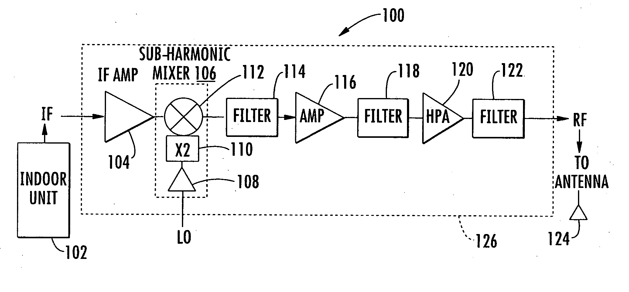
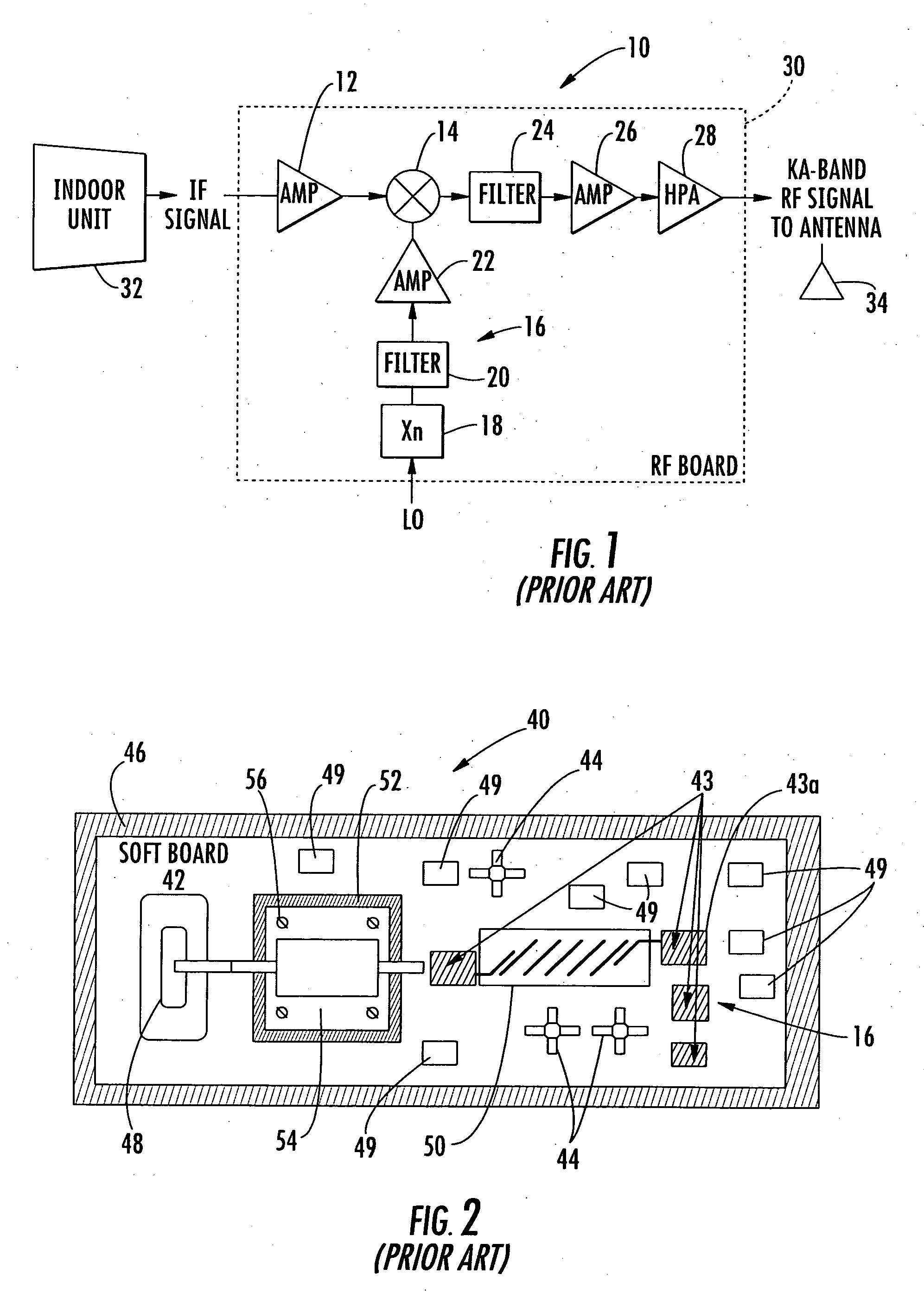
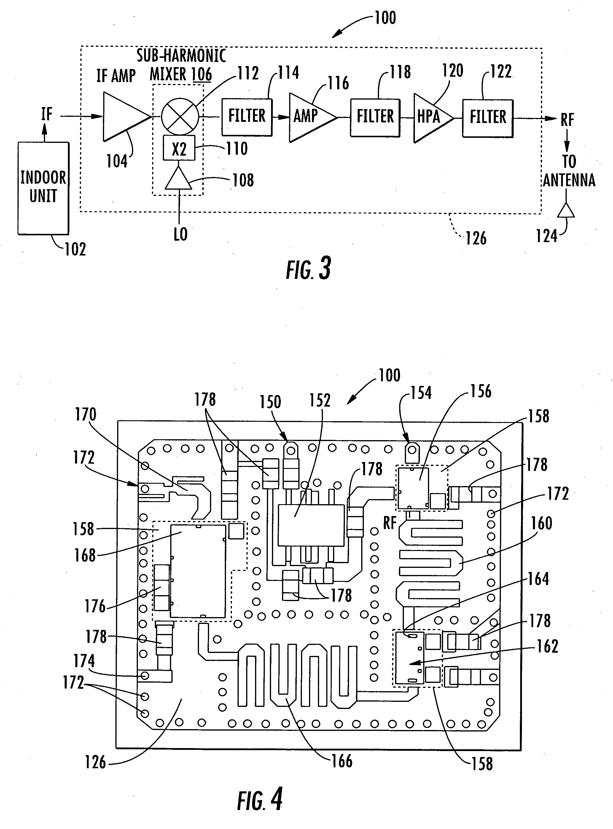
[0029] One prior art method of building Ka-band and similar wavelength Block Up Converters (BUC's) is to prepackage MMIC chips in surface mount packages, which in turn, are secured to a board using traditional SMT assembly methods to produce the final BUC product. Although this method is widely used by many manufacturers, it has not been successful for driving down the ma...


PUM


Abstract

A Block Up Converter (BUC) chip includes a base board with opposing top and bottom metal layers and having radio frequency (RF) circuits at the top metal layer and ground and signal pads at the bottom metal layer. Microwave Monolithic Integrated Circuit (MMIC) chips are carried by the base board and operative with the RF circuits and ground and signal pads for receiving and up converting signals. A top cover protects the MMIC chips.

Description

FIELD OF THE INVENTION [0001] The present invention relates to the field of communications, and more particularly, this invention relates to the field of Block Up Converters (BUC's), for example, used in Very Small Aperture Terminal (VSAT) communications systems. BACKGROUND OF THE INVENTION [0002] In the early days of satellite communications, there were few downlink earth stations. Those few stations in existence were essentially large antenna dishes operative with wired communications hubs. Any communications signals received at these large earth stations were distributed through wires and cables to numerous destinations, including other communications hubs. As a result, many earth stations were positioned in metropolitan areas and acted as communications hubs, which distributed communication signals in broadcast fashion to other communications hubs, regional communications centers, or local home and residence sites via cable. It was not convenient to have a large number of smalle...

Claims


Application Information

Patent Timeline
Patent Type & Authority Applications(United States)
IPC IPC(8): H04B1/04H01Q11/12H04B1/10
CPCH01L23/04H01L23/552H01L23/66H01L2224/32225H01L2224/48091H01L2224/48227H01L2224/73265H01L2924/01079H01L2924/1423H01L2924/15153H01L2924/1517H01L2924/16153H01L2924/1617H01L2924/19041H01L2924/19105H04B1/04H01L2924/00014H01L24/48H01L2924/00H01L2924/14H01L2224/45099H01L2224/45015H01L2924/207
Inventor AMMAR, DANNY F.
Owner REVEAL IMAGING
Why Eureka
Try Eureka