
Patellar cutting guide

a cutting guide and patellar technology, applied in the field of total knee arthroplasty, can solve the problems of pain, stiffness, swelling, and permanent cartilage deterioration, and achieve the effects of minimizing the length of the peg, reducing the profile of the component, and low profil

Inactive Publication Date: 2006-07-20
SMITH & NEPHEW INC
View PDF16 Cites 119 Cited by
  • Summary
  • Abstract
  • Description
  • Claims
  • Application Information

AI Technical Summary

Benefits of technology

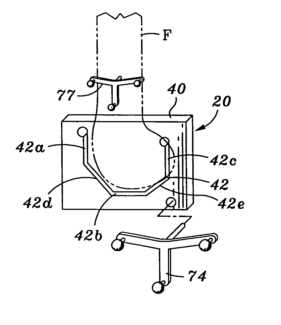
[0021] A patellar cutting guide is provided for resecting the patella without dissecting the overlying skin, subcutaneous tissues and bursa from the patella, lessening the chance of skin necrosis from subcutaneous dissection, and lessening the chance of knee tenderness and inability of the patient to kneel after total knee replacement.
[0028] In one embodiment, the femoral knee component is generally “C” shaped and includes a trough-shaped inner surface. The profile of the component is minimized along the inner surface to permit the femoral knee component to be inserted transversely through the medial or lateral incision and aligned with the resected femur, including without substantial dislocation of the femur relative to the tibia. To this end, in one embodiment, one or more engaging pegs extend outwardly from the inner surface for engaging one or more recesses in the femur, the length of the pegs minimized. In one embodiment, the femoral knee component is of the posterior cruciate ligament substituting design and includes a cam for engagement by a post on a mating tibial knee component. In one embodiment, the cam has a low profile, extending between a pair of condyle portions of the component and not extending upwardly into the trough area of the component, again minimizing the profile of the component.

Problems solved by technology

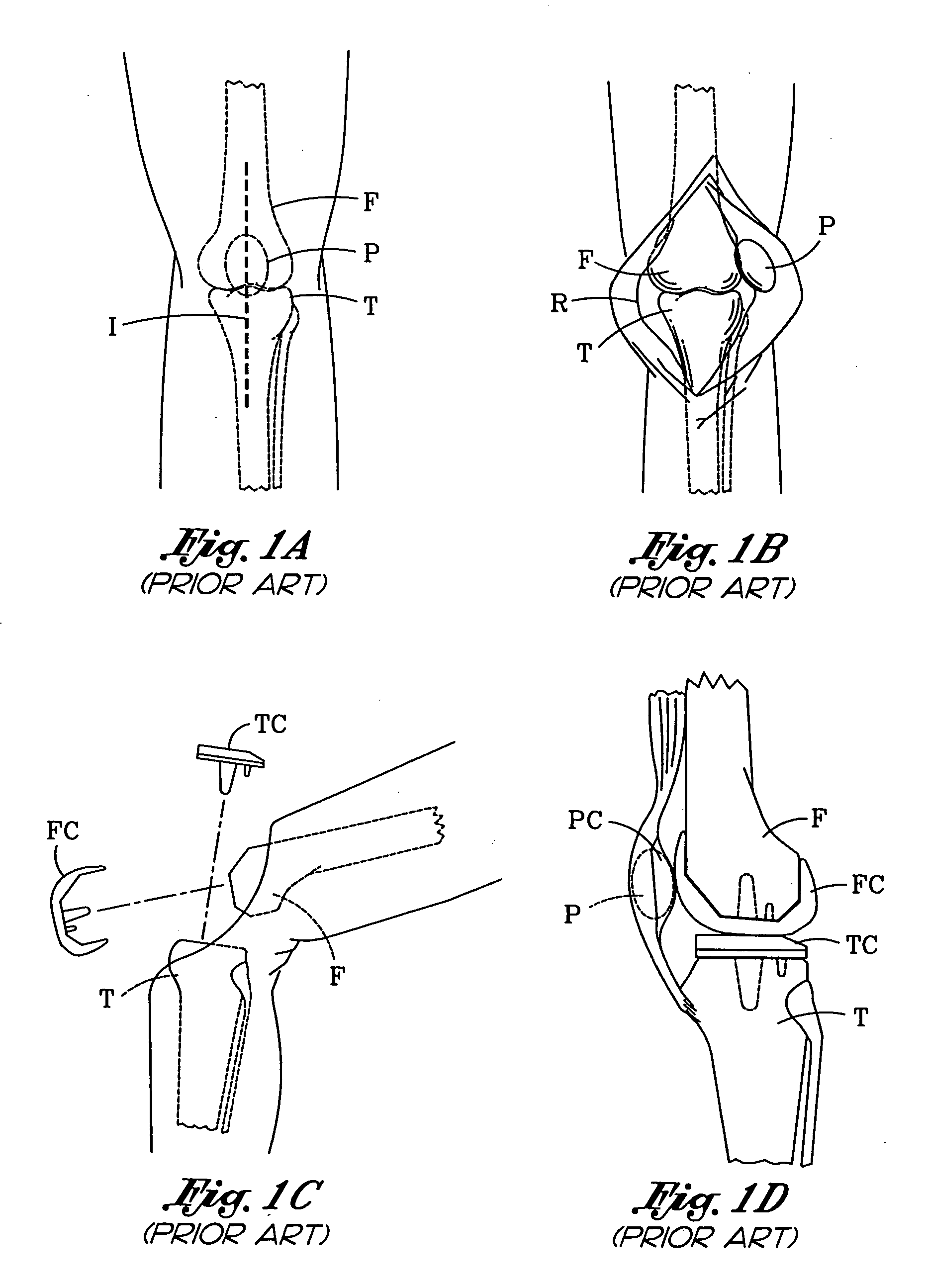
For example, excessive deterioration of knee cartilage may necessitate knee replacement.
This type of problem and other injuries to the knee may result from accidents, disease such as osteo-arthritis or rheumatoid arthritis, or other causes.
However, certain conditions, most commonly arthritis, can cause permanent deterioration of the cartilage.
When the cartilage wears away, the roughened surfaces of the femur, tibia and patella may rub against each other causing pain, stiffness and swelling.
One significant problem is that the procedure is quite invasive and traumatizing.
The procedure results in a large incision and substantial stresses upon the body resulting in long periods of recovery / rehabilitation, and extended periods of hospitalization.
This stretching results in substantial strain and traumatization to the extensor mechanism and quadriceps muscle which takes a great deal of time to recover.
In fact, in many instances a patient can not actively extend the knee for several days after the procedure.
Additionally, the patellar tendon, on occasion, is ruptured or pulled loose from the tibia due to excessive strain with eversion of the patella.
This strains and traumatizes the ligaments of the knee and may result in damage to the adjacent nerves and blood vessels or lead to complication including blood clots, nerve palsy, arterial injury, excessive swelling, fracture or ligament avulsion.
Use of a smaller frontal incision places excess tension on the skin, often resulting in skin necrosis or delayed healing.
The large incision results in a long period of recovery and generally results in a visible scar.

Method used


Image

  • Patellar cutting guide
  • Patellar cutting guide
  • Patellar cutting guide

Examples


Embodiment Construction

[0059] The invention is a method and apparatus for total knee arthroplasty. In the following description, numerous specific details are set forth in order to provide a more thorough description of the present invention. It will be apparent, however, to one skilled in the art, that the present invention may be practiced without these specific details. In other instances, well-known features have not been described in detail so as not to obscure the invention.

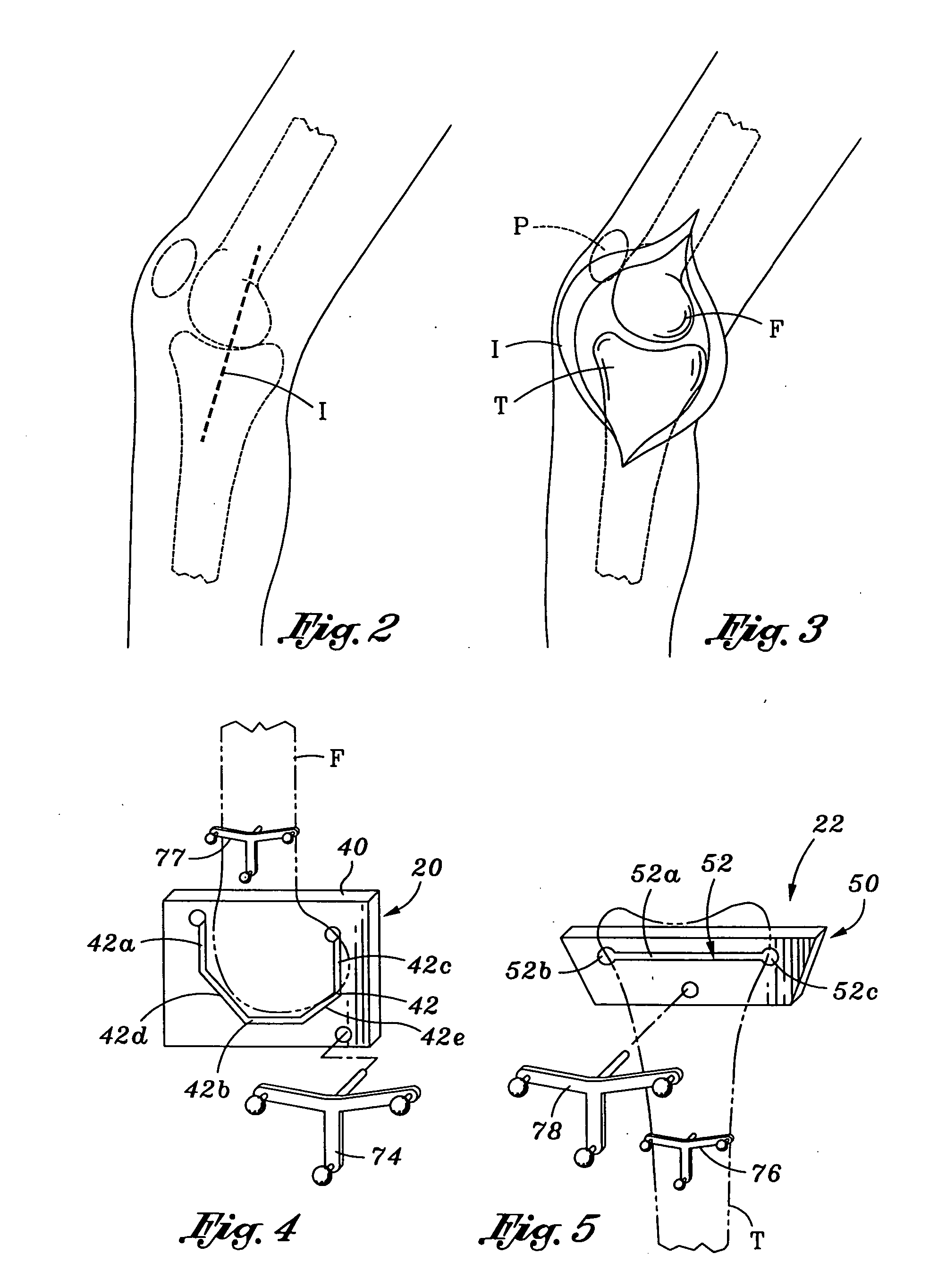
[0060] One embodiment of the invention is a method for total knee replacement which is minimally invasive. Referring to FIG. 2, in accordance with the method, an incision I is made either generally medially or laterally along the mid-lateral line of the knee. By “generally” medially or laterally, it is contemplated that the incision I may be somewhat anterior or posterior to the mid-lateral line. So located, the incision I is generally centered over the tibio-femoral or “knee” joint. In a preferred embodiment, the incision I is ...


PUM


Abstract

A patellar cutting guide is particularly useful in a method of minimally invasive knee arthroplasty in which an incision is made along the medial or lateral aspect of a patient's knee, exposing the knee joint. The patellar cutting guide includes a clamp configured to be located exterior to the knee over the anterior portion of the patella, a stop having at least one portion configured to extend through an incision to a location posterior to the patella, and a cutting guide defining a cutting slot. The clamp may have outwardly extending spikes for passage through the tissue overlying the patella and into engagement with the patella. The stop is movable relative to the clamp and / or cutting guide. In one embodiment, the cutting guide is offset laterally and posteriorly relative to the clamp so that the slot is aligned with a medially or laterally-formed incision in the knee.

Description

RELATED APPLICATION [0001] This application is a continuation of U.S. application Ser. No. 10 / 143,203 filed May 10, 2002.FIELD OF THE INVENTION [0002] The present invention relates to methods and apparatus for total knee arthroplasty. BACKGROUND OF THE INVENTION [0003] Total knee replacement (also known as total knee arthroplasty) surgery is a common procedure that is performed on hundreds of thousands of people each year. A number of circumstances may require replacement of a person's knee. For example, excessive deterioration of knee cartilage may necessitate knee replacement. This type of problem and other injuries to the knee may result from accidents, disease such as osteo-arthritis or rheumatoid arthritis, or other causes. [0004] The knee joint or “knee” is formed by the bottom or distal end of the femur (or “thigh bone”) which extends from the hip, the top or proximal end of the tibia (or “shin bone”) which extends to the ankle, and the patella (or “knee cap”). The distal end...

Claims


Application Information

Patent Timeline
Patent Type & Authority Applications(United States)
IPC IPC(8): A61F5/00A61B17/15A61B17/56A61B19/00A61F2/38
CPCA61B17/155A61B17/157A61B17/158A61B19/5244A61B2017/564A61B2019/502A61B2019/505A61B2019/5255A61B2019/5272A61B2019/5483A61F2/3886A61B2090/3983A61B2034/102A61B2034/2055A61B2034/2072A61B34/20A61B2034/105
Inventor SWANSON, TODD V.
Owner SMITH & NEPHEW INC
Learn More