
Knee joint prosthesis

a knee joint and prosthesis technology, applied in knee joints, prosthesis, medical science, etc., can solve the problems of shortening the member (namely the post structure) of the tibial insert wears off rapidly, and even fractures, so as to achieve the effect of increasing the life span of the prosthetic knee join

Inactive Publication Date: 2006-07-20
CHENG CHENG KUNG
View PDF33 Cites 50 Cited by
  • Summary
  • Abstract
  • Description
  • Claims
  • Application Information

AI Technical Summary

Benefits of technology

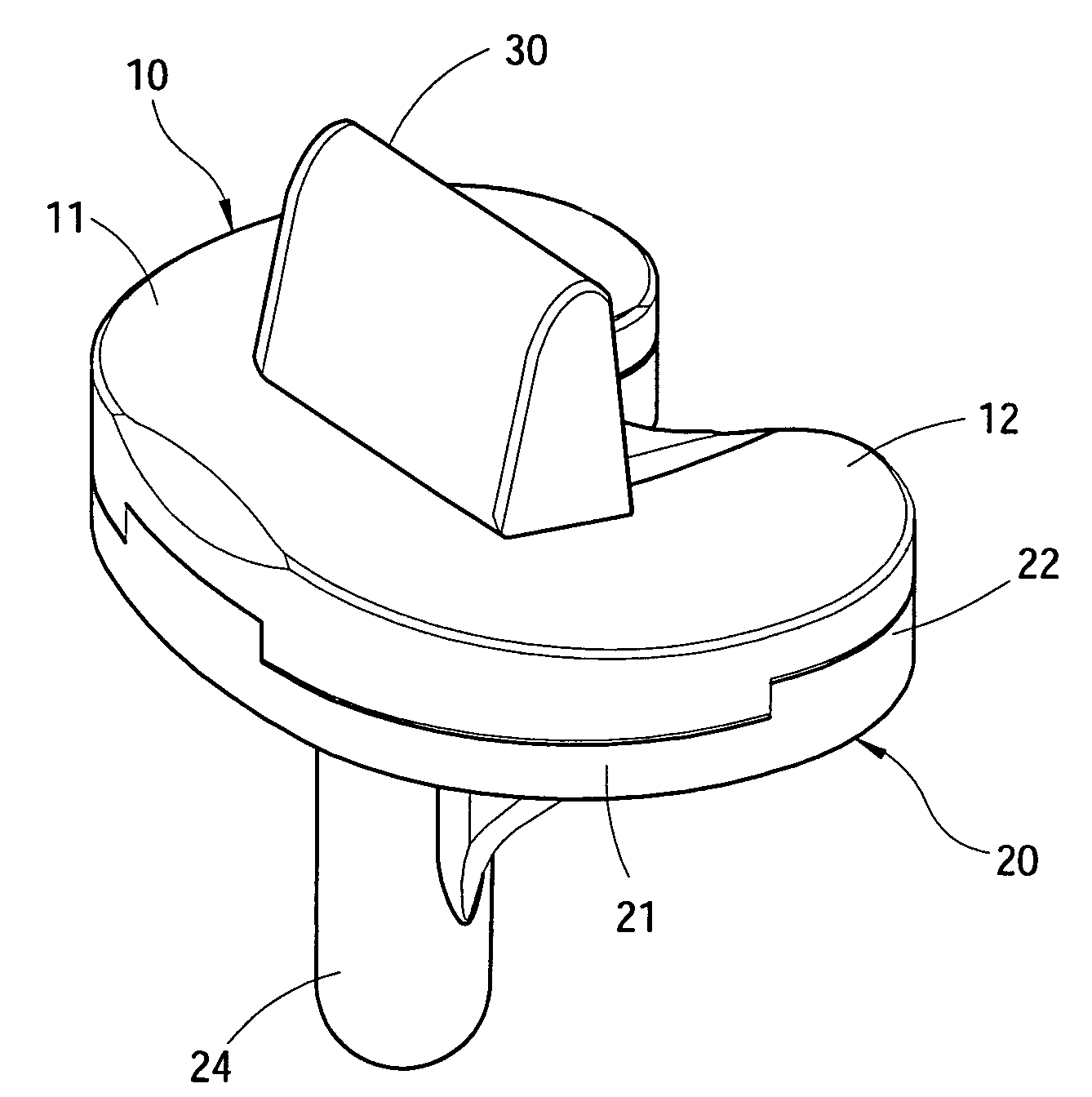
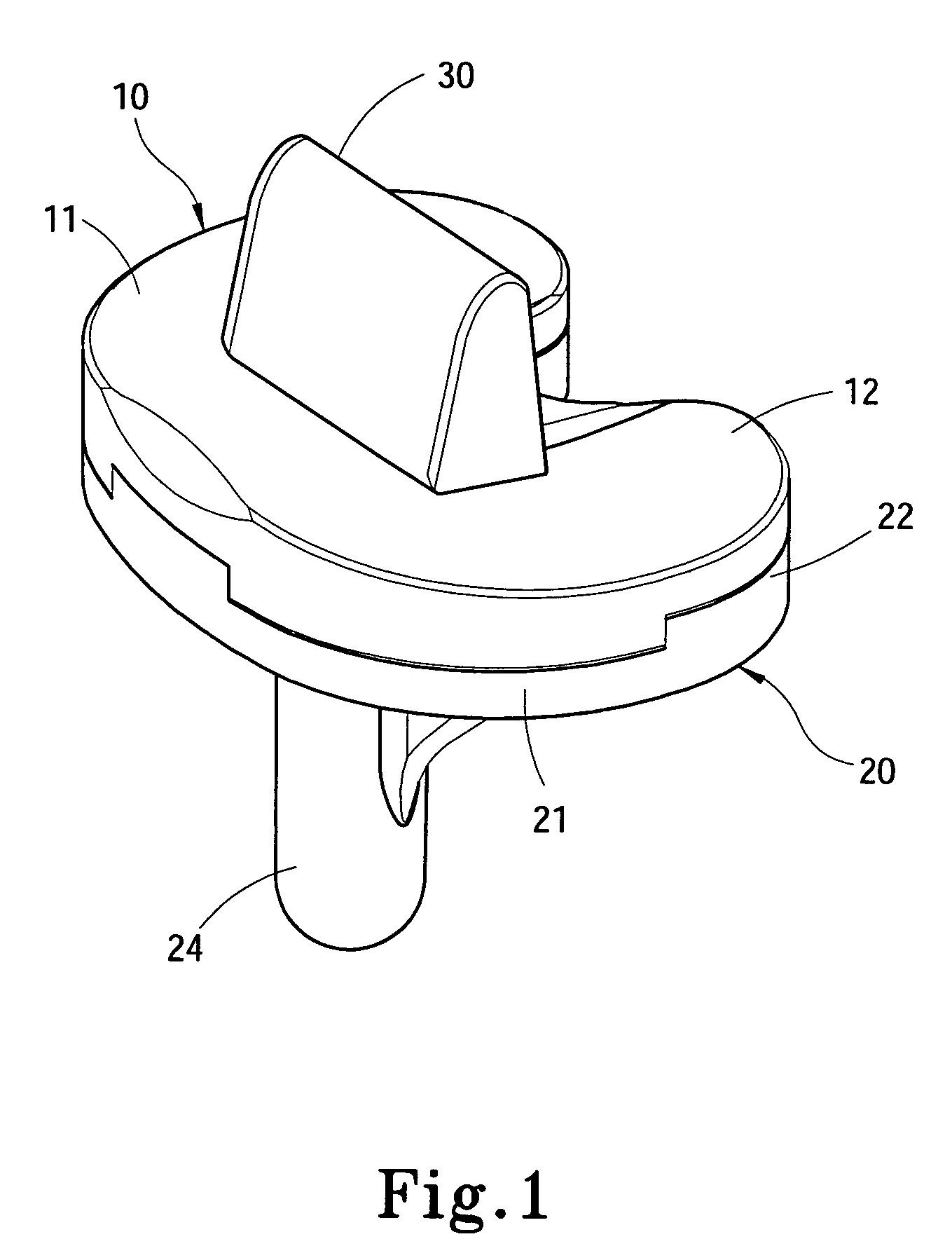
[0006] The primary object of the invention is to solve the aforesaid disadvantages. The invention employs a separate design and has a moving aperture on a tibial insert to hold a bracing member which is coupled with a femur implanted component. A tibial insert is provided that has a retaining member. The bracing member and the retaining member may be swiveled in the moving aperture. The bracing member is made from a wearing-resistant material and can prevent the tibial insert from sliding and wearing off, thus the life span of the prosthetic knee joint increases.

Problems solved by technology

However, clinical diagnoses over the years show that such type of prosthetic knee joint still has drawbacks that affect its life span, notably:
As the femur implanted component is made of metal, while the tibial insert is made from polyethylene, when the femur implanted component swivels is coupled with the bracing member and swivels like screw-home mechanism, due to the difference of materials and the fixed bracing member of the tibial insert, the bracing member (namely post structure) on the tibial insert wears off rapidly and even fractures.
These wearing phenomena not only shorten the life span of the prosthetic knee joint but also produce polyethylene debris, induce osteolysis, and lead components loosening.

Method used


Image

  • Knee joint prosthesis
  • Knee joint prosthesis
  • Knee joint prosthesis

Examples


Embodiment Construction

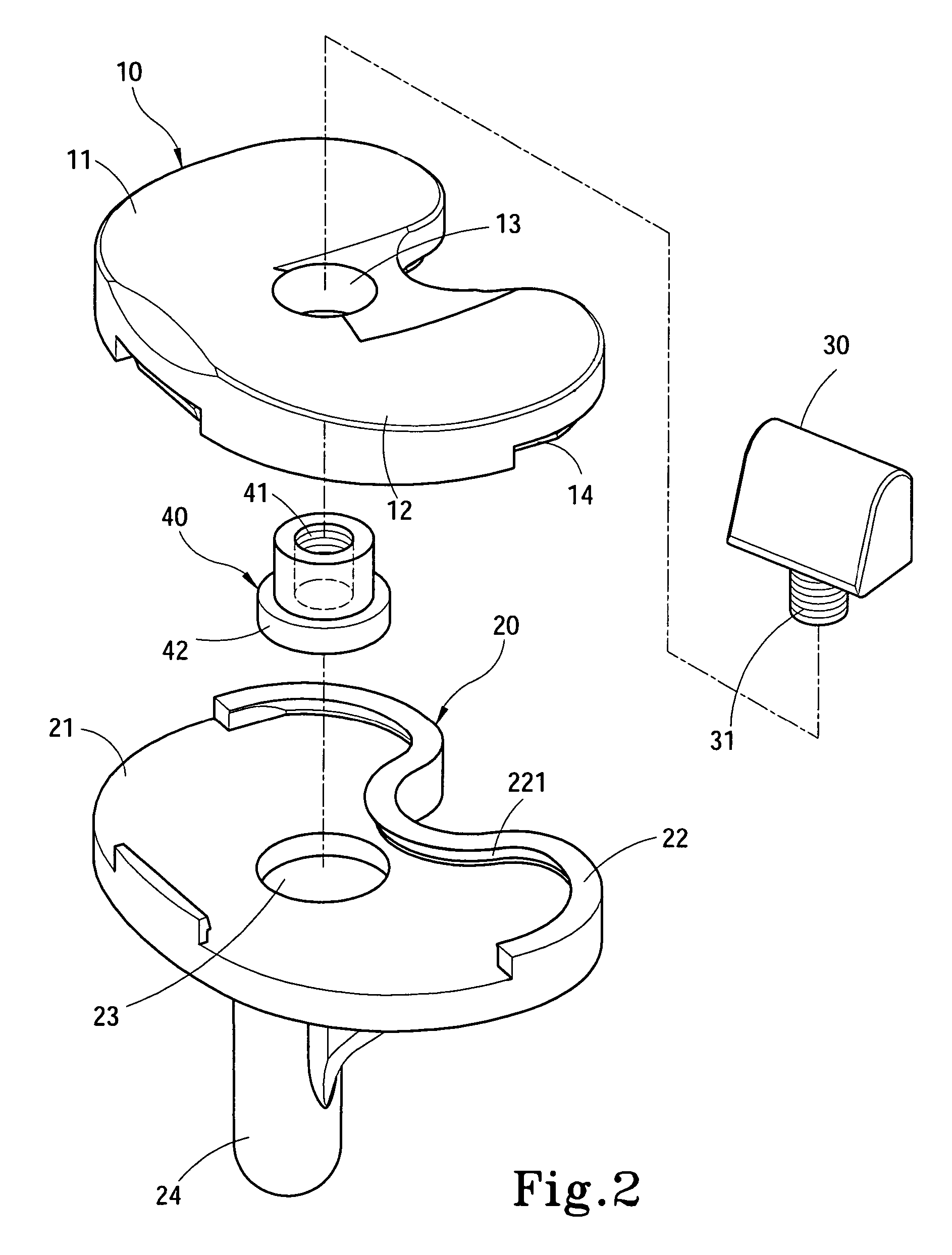
[0015] Please refer to FIGS. 1, 2, 3 and 5, the prosthetic knee joint according to the present invention is located between a thighbone 50 and a tibia 70, and is coupled with an femur implanted component 60 fastened to the thighbone 50 to enable a patient to resume normal movements. The prosthetic knee joint includes a tibial insert 10 coupled with the femur implanted component 60 and a tibial baseplate 20 coupled with the tibial insert 10.

[0016] The tibial insert 10 has two concavities 11 and 12 that allow the femur implanted component 60 to move thereon. The tibial insert 10 further has a moving aperture 13 formed between the two concavities 11 and 12. The moving aperture 13 holds a bracing member 30 which is coupled with the femur implanted component 60. The bracing member 30 has a fastening section 31.

[0017] The tibial baseplate 20 has a holding surface 21 to hold the tibial insert 10, a retaining member 40 which has an anchor section 41 mating the fastening section 31, and an...


PUM


Abstract

An improved knee joint prosthesis located between a thighbone and a tibia to couple with a femur implanted component to allow a patient to resume normal movement and exercise. The knee joint prosthesis adopts a separate design, and includes a tibial insert which has a moving aperture to hold a bracing member coupled with the femur implanted member and a tibial baseplate which has a retaining member. The bracing member and the retaining member are swivelable in the moving aperture, and the bracing member is made from wearing resistant material, so that sliding and wearing that might otherwise occur to the tibial insert may be prevented. Therefore the life span of the posterior stabilized knee joint prosthesis increases.

Description

FIELD OF THE INVENTION [0001] The present invention relates to an improved knee joint prosthesis and particularly to a prosthetic knee joint to bridge a thighbone and a tibia and to couple with a femur implanted component on the thighbone to enable a patient to resume normal movement and exercise. BACKGROUND OF THE INVENTION [0002] The knee joint prosthesis is first developed by Gunston et al in 1968. It mainly aims to substitute an impaired or degenerated knee joint that cannot function normally. It is made of metal to imitate the condyle of the femur and uses ultra high molecular weight polyethylene (UHMWPE) to substitute the function of knee joint and meniscus cartilage. In 1970s, varying prosthetic knee joints have been developed. Development of the knee prosthesis generally follows two directions. One recommends scarifying the posterior cruciate ligament (PCL) during surgical operation. The other one suggests retaining the posterior cruciate ligament during the surgical operati...

Claims


Application Information

Patent Timeline
Patent Type & Authority Applications(United States)
IPC IPC(8): A61F2/38
CPCA61F2/3868A61F2/3886
Inventor CHENG, CHENG-KUNGHUANG, CHANG-HUNG
Owner CHENG CHENG KUNG
Learn More