
Narrowband detector

a detector and narrowband technology, applied in the field of detector arrangements, can solve problems such as poor tracking, and achieve the effects of reducing jitter, improving accuracy and responsiveness, and smoothing bandwidth control signals

Inactive Publication Date: 2006-07-20
TECTEON
View PDF0 Cites 42 Cited by
  • Summary
  • Abstract
  • Description
  • Claims
  • Application Information

AI Technical Summary

Benefits of technology

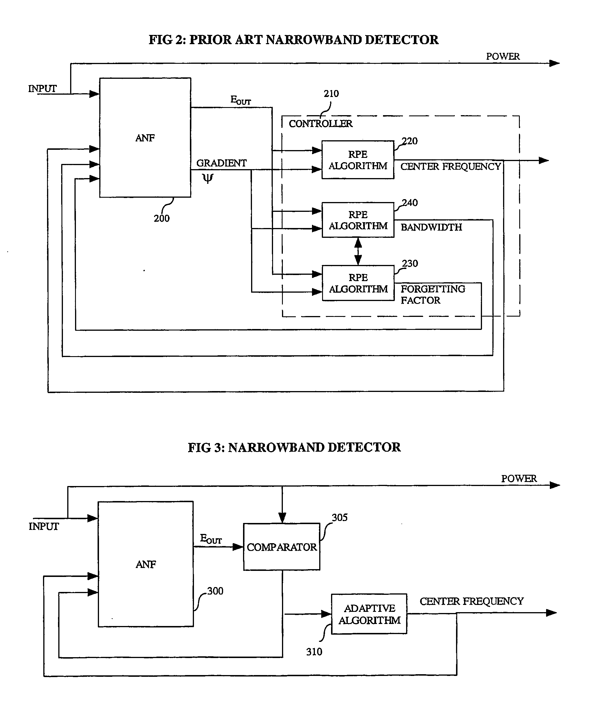
[0014] Better control of the filter can be achieved by basing the filter control on this comparison. The comparison gives a more direct measure of how well the filter is tracking the narrowband signal. In the case of a notch filter, if the output is large relative to the input, this indicates poor tracking. The control should be biased rapidly towards improved tracking speed. Correspondingly, a small output relative to the input, indicates good tracking and the control should be biased towards accuracy of tracking, at the expense of speed of tracking. This improvement in turn enables critical speed and accuracy of detection requirements to be met with less computationally intensive algorithms than previously. It also enables better detection of multiple narrowband signals since there is little possibility of the above mentioned problem of convergence to a minimum error with the bandwidth covering two closely spaced narrowband signals. Using the input signal can effectively prevent this.
[0028] multiplying the input by a previous output of the process, subtracting the result from a constant, and multiplying the result of the subtraction by the previous output. This enables the amount of processing to be reduced considerably. For 32-bit precision for example a division will require about 32“*” and 32“+” operations. In the case of the pseudo division, it can be reduced to: 2“*” and 2“+” operations, so it can be at least 16 times faster. It uses an approximation as explained below, which is sufficiently accurate provided the input is a series of values having only small changes between consecutive values.

Problems solved by technology

In the case of a notch filter, if the output is large relative to the input, this indicates poor tracking.

Method used


Image

  • Narrowband detector
  • Narrowband detector
  • Narrowband detector

Examples


Embodiment Construction

FIG. 3, Narrowband Detector

[0048]FIG. 3 shows a narrowband detector according to a first embodiment of the invention. It could be applied in the arrangement shown in FIG. 1 or in other applications. There is an ANF 300, which is fed by the input signal, and by one or more control signals from the controller which uses an adaptive algorithm 310. These control signals include the centre frequency. Other control signals may optionally be used, such as bandwidth. The ANF outputs a residual error power signal Eout which is compared to the input signal by a comparator 305. The relationship between these signals is used to control the ANF, either directly, or by influencing the controller. Other outputs of the ANF may also be used by the controller. As ANFs are well known and can be implemented without difficulty, there is no need to describe this function in more detail, and the reader is referred to appropriate text books or other publications, including those referenced above. In princi...


PUM


Abstract

A narrowband signal detector has an adaptable filter and controller for controlling the centre frequency and the bandwidth of the filter, to track the narrowband signal. Better control of the filter can be achieved by basing the filter control on a comparison of output and input to the filter. The comparison gives a more direct measure of how well the filter is tracking the narrowband signal. In the case of a notch filter, if there is poor tracking. The control should be biased rapidly towards improved tracking speed. Otherwise, for good tracking, the control should be biased towards accuracy of tracking. This enables speed and accuracy of detection requirements to be met with less computational load. Applications include telecommunications signalling or data tone detection. Multiple narrowband signals can be detected by a cascade of filters.

Description

FIELD OF THE INVENTION [0001] The invention relates to detector arrangements including software and apparatus for detecting narrowband signals, to tone processing arrangements, to apparatus for a central office, to pseudo division circuitry or software, to methods of using an output of such arrangements for control or monitoring purposes, to methods of transmitting voice or data using such arrangements, and to methods of offering a voice or data transmission service using the above. BACKGROUND TO THE INVENTION [0002] Detection of narrow-band signals such as tones is used in many fields, including imaging fields such as radar- and sonar-type signal processing, accoustic signal processing, including mechanical vibration detection, and telecommunications. Telecommunication equipment make a heavy use of tones for signaling purposes. Some examples of tone signaling systems are DTMF (dual tone multi-frequency) and MF (multi-frequency) signaling. As a consequence, a variety of different eq...

Claims


Application Information

Patent Timeline
IPC IPC(8): G10L19/02H03H21/00
CPCH03H21/0012
Inventor FOURET, JOACHIM
Owner TECTEON
Learn More