Cooling system for a transition bracket of a transition in a turbine engine

Active Publication Date: 2006-07-27
SIEMENS ENERGY INC
View PDF15 Cites 11 Cited by
  • Summary
  • Abstract
  • Description
  • Claims
  • Application Information

AI Technical Summary

Benefits of technology

[0003] This invention relates to a heat shield for a transition bracket in a can-annular combustion system of a turbine engine, whereby the transition bracket is used to couple a transition to a blade ring or other component of a turbine blade assembly to direct comb

Problems solved by technology

This large temperature differential often causes premature failure of

Method used


Image

  • Cooling system for a transition bracket of a transition in a turbine engine
  • Cooling system for a transition bracket of a transition in a turbine engine
  • Cooling system for a transition bracket of a transition in a turbine engine

Examples


Example

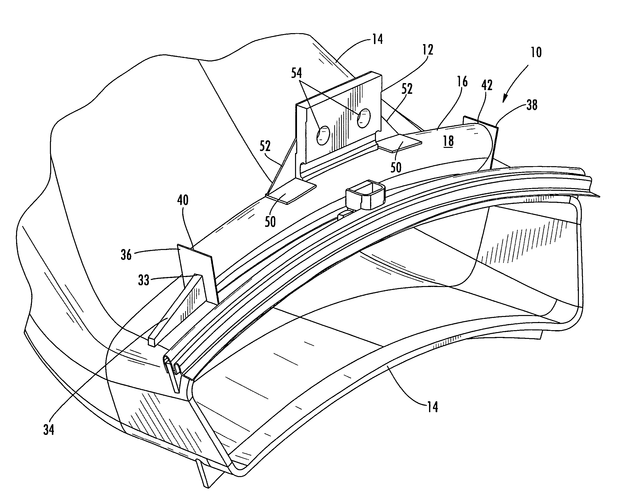
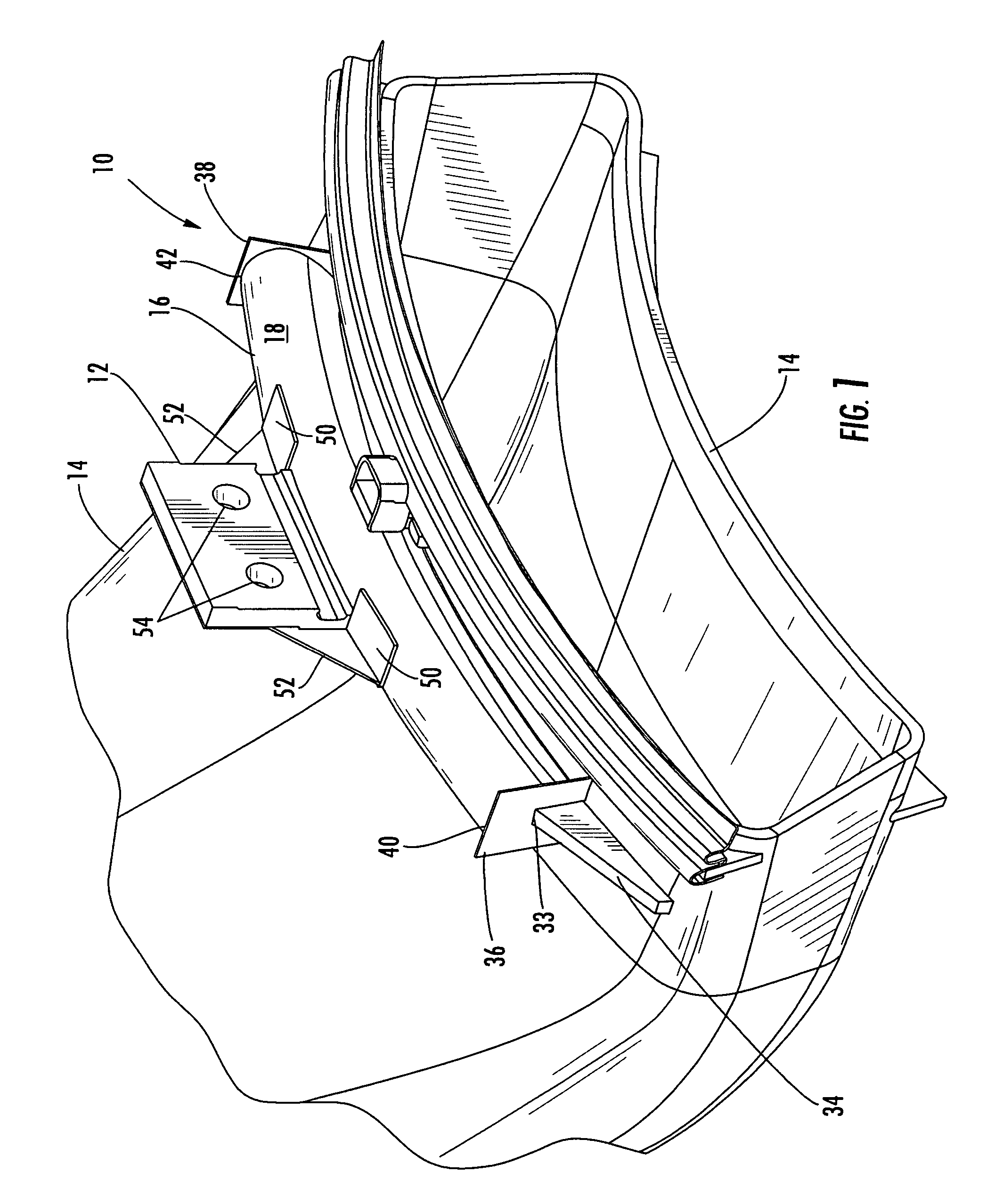
[0017] As shown in FIGS. 1-7, this invention is directed to a heat shield 10 for a transition bracket 12 in a can-annular combustion system of a turbine engine. The heat shield 10 is configured to insulate the transition bracket 12 and a transition bracket rib 34 from cooling gases found in turbine engines. By insulating the transition bracket 12 and the transition bracket rib 34 from cooling gases, the transition bracket 12 and the transition bracket rib 34 do not experience as large a temperature differential across the length of the transition bracket 12 and the transition bracket rib 34. As a result, the transition bracket 12, the transition bracket rib 34, and the transition 14 are less prone to premature failure.

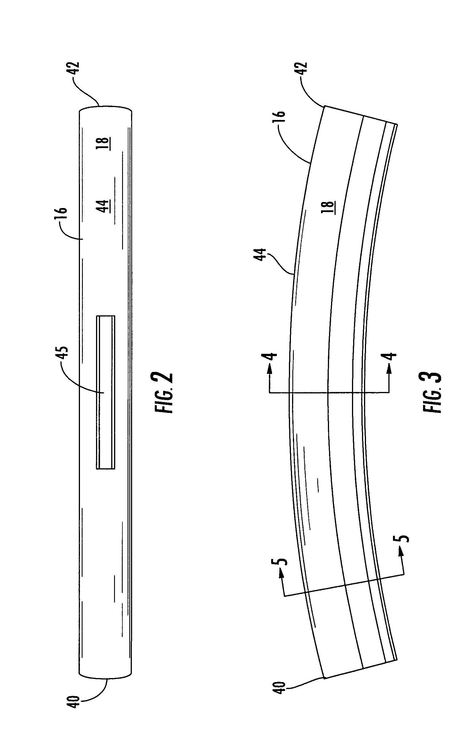
[0018] As shown in FIGS. 1-3, the heat shield 10 is formed from an elongated body 16 that is configured to be attached to a transition 14 of a combustion system of a turbine engine. In at least one embodiment, the elongated body 16 is configured to be attached to a tr...


PUM


Abstract

A heat shield for a transition of a turbine engine for coupling a transition component of a turbine engine to a turbine vane assembly to direct combustor exhaust gases from the transition into the turbine vane assembly. The heat shield may be capable of reducing the temperature differential across a transition bracket extending from a transition component, thereby reducing the likelihood of premature failure of the bracket or the transition, or both. The heat shield may reduce the temperature differential by insulating the transition bracket and transition bracket rib from cooling gases. The heat shield may be formed from a tubular elongated body having first and second end attachments configured to attach the elongated heat shield body to the transition.

Description

FIELD OF THE INVENTION [0001] This invention is directed generally to transitions in turbine engines between combustors and turbine vane assemblies for directing exhaust gases into the turbine vane assemblies and, more particularly, to devices for cooling turbine brackets used to attached transitions in turbine engines. BACKGROUND [0002] Typically, gas turbine engines operate at high temperatures that may exceed 2,500 degrees Fahrenheit. During operation, turbine engines expose turbine vane assemblies, transitions, and other components to these high temperatures. As a result, these components must be made of materials capable of withstanding such high temperatures. Typically, transition sections are coupled to a blade ring or other component of a turbine vane assembly. The transition sections are often attached using a bracket. During operation, the bracket is heated on one edge by the transition and cooled on another edge by cooling gases. As a result, a large temperature different...

Claims


Application Information

Patent Timeline
IPC IPC(8): F23R3/42
CPCF01D9/023F01D25/12F05D2260/20
Inventor YOUNGBLOOD, BRADLEY T.
Owner SIEMENS ENERGY INC
Why Eureka
Try Eureka