Gas sensor and method for production thereof

a technology of gas sensor and production method, which is applied in the field of gas sensor, can solve the problems of high risk of cracking, complex manufacturing technology for sealing between the molded ceramic part and the housing, and often unavoidable slight warping of the sensor elements, and achieves the effect of cost-effective and simple production technology

Inactive Publication Date: 2006-07-27
ROBERT BOSCH GMBH
View PDF15 Cites 16 Cited by
  • Summary
  • Abstract
  • Description
  • Claims
  • Application Information

AI Technical Summary

Benefits of technology

[0006] The gas sensor according to the present invention and the method according to the present invention for producing the gas sensor provide that a sensor element is sealed in a housing using at least one sealing element in a cost-effective manner involving simple production technology, the sensor element being unaffected by vibrations that occur during operation. To this end, the sealing element is placed in a metal receptacle, which in turn is affixed to the metal housing, and the sealing element encloses the sensor element centered along a longitudinal extension L or on the side facing the measuring gas.
[0007] The sensor element is held primarily by the sealing element in the metal receptacle (as well as to a lesser degree by the contacting). This eliminates the need for one molded ceramic part, so that the metal receptacle may be exposed directly to the measuring gas.
[0008] The sealing element may include glass or glass ceramic, and forms a positive material connection with the sensor element and the molded metal part. A glass seal or a glass ceramic seal is able to adapt itself to the shape of the sensor element. This makes it possible to hold even warped sensor elements securely. To prevent mechanical stresses under temperature fluctuations, the expansion coefficient of the sealing element and the expansion coefficient of the sensor element differ by no more than 10 percent.
[0012] An especially simple and cost-effective manufacture of the gas sensor is possible if the space from the sensor element to the side wall of the cup-shaped metal receptacle is less than or equal to twice the height of the sensor element at least in some places. The height of the sensor element refers to the extension of the sensor element perpendicular to its large surface.
[0013] In a first further development of the present invention, the metal receptacle contains a first and a second sealing element. The two sealing elements contain glass or glass ceramic as their main component, and are placed one behind the other in the receptacle in the longitudinal direction of the sensor element. The glass-forming component of the first sealing element, which faces the measuring gas, has a higher melting point than the glass-forming component of the second sealing element, which faces away from the measuring gas. When the sensor element is installed, the composite of metal receptacle, first and second sealing element, and sensor element is heated to a temperature at which the glass-forming component of the second sealing element completely melts, while the glass-forming component of the first sealing element does not melt or does not do so completely. This configuration of the sealing elements results in the second sealing element forming a gas-tight, positive material connection to the sensor element and metal receptacle, and the first sealing element preventing the glass of the second sealing element from being able to flow out of the receptacle. The configuration may also provide for the second sealing element to be positioned between the first sealing element and a third sealing element, the third sealing element having a viscous consistency at the temperatures at which the gas sensor is used. This configuration of the sealing elements reduces the risk of the glass or the glass ceramic cracking and the risk of the sensor element breaking in the area of the transition from the glass or the glass ceramic to the air.
[0014] In a second further development of the present invention, the metal receptacle includes a first and a second sealing element, which are positioned in the receptacle, one behind the other in the longitudinal direction of the sensor element. The first sealing element, which faces the measuring gas, contains a sintered ceramic, and the second sealing element, which faces away from the measuring gas, contains a glass or a glass ceramic. The first sealing element prevents the glass or the glass ceramic of the second sealing element from flowing out of the ceramic receptacle during manufacturing of the gas sensor. In addition, a wafer of pressed ceramic powdered material may be provided between the first and second sealing element as a third sealing element.

Problems solved by technology

The gas sensor discussed in German Published Patent Application No. 197 07 456 provides that when a seal is introduced into a molded ceramic part, the danger of cracking is high due to temperature fluctuations during operation of the gas sensor.
In addition, the sealing between the molded ceramic part and the housing requires complex manufacturing technology.
In this process, slight warping of the sensor elements is often unavoidable.
Since the sensor element is fixed only at its end facing the contacting by a positive material connection, the sensor element is able to vibrate in the recess due to the vibrations that occur in operation, which may result in damage to the sensor element.
Furthermore, building the sensor element into the rigid molded ceramic part is complex, requires difficult production techniques, and may damage the sensor element.

Method used


Image

  • Gas sensor and method for production thereof
  • Gas sensor and method for production thereof
  • Gas sensor and method for production thereof

Examples


Embodiment Construction

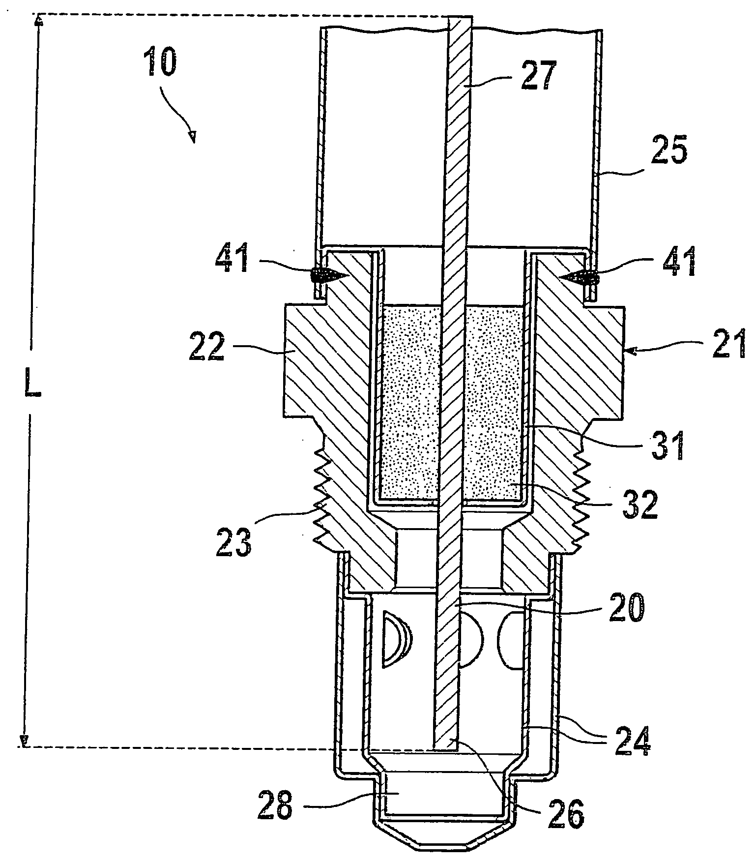
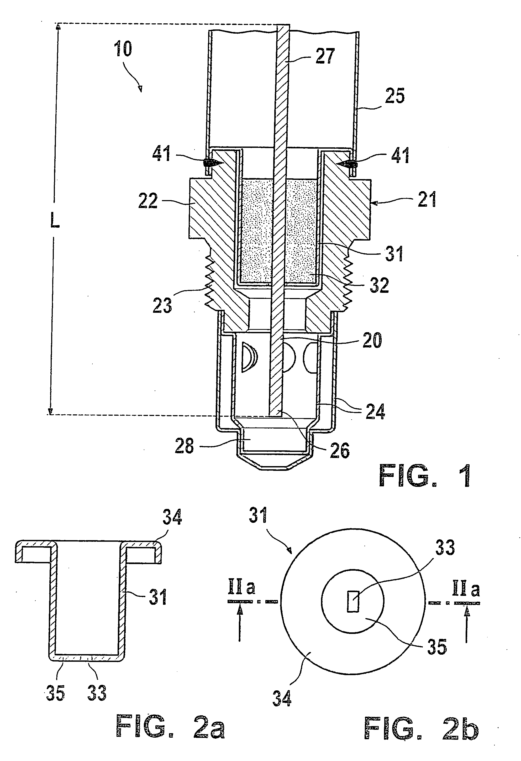
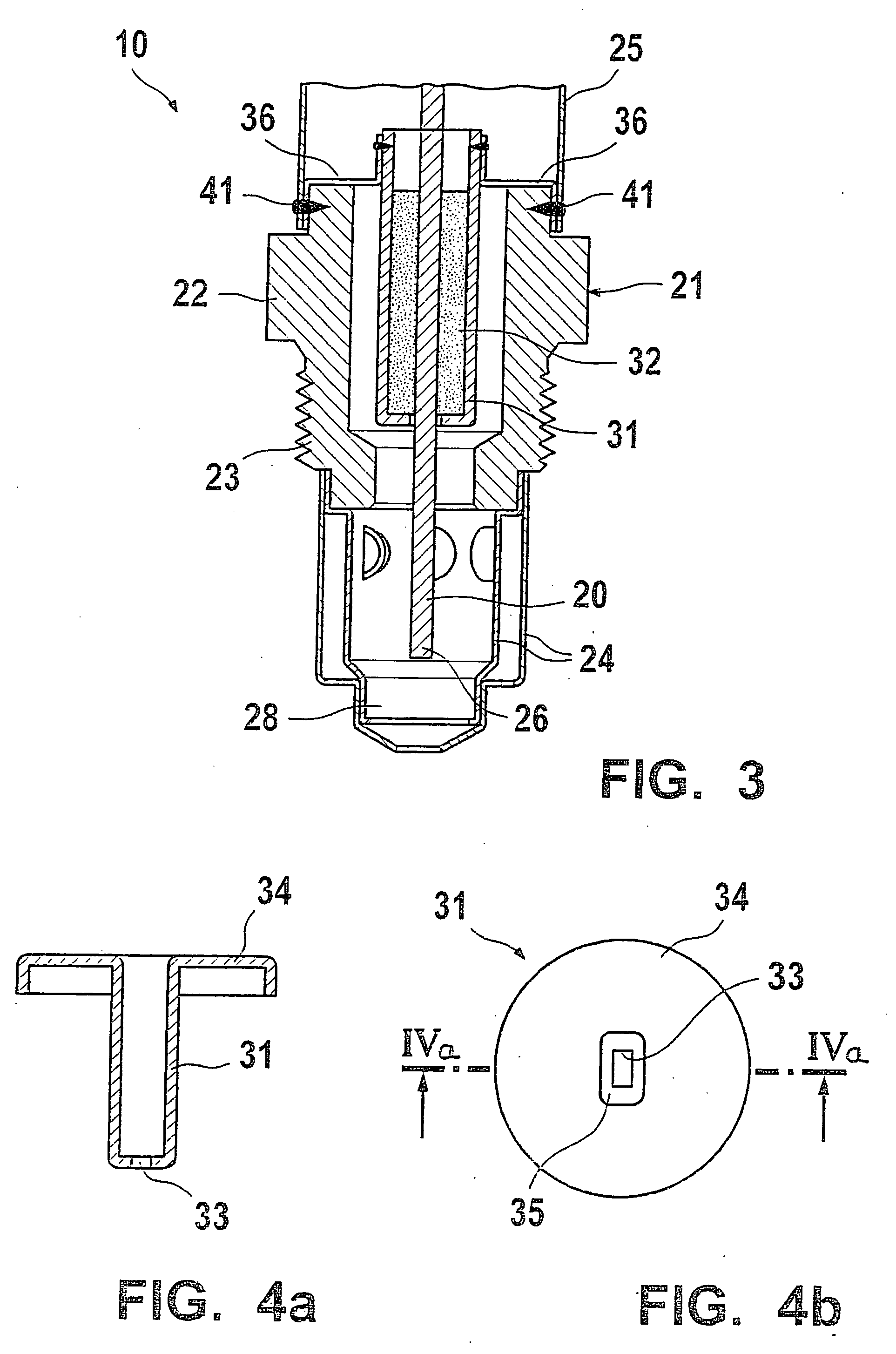
[0026]FIG. 1 shows a section of a gas sensor 10 as a first exemplary embodiment of the present invention. Gas sensor 10 is used for example to determine the temperature or the oxygen content of a measuring gas, and may be built into a measuring opening of an exhaust line of a combustion engine (not shown). Gas sensor 10 exhibits a housing 21 including threading 23 and a hexagon 22 for this purpose. Housing 21 encloses a planar, elongated sensor element 20, which is configured as a ceramic multi-layer system. On a first section 26, which is exposed to the measuring gas, sensor element 20 includes measuring elements such as electrodes or heaters. First section 26 of sensor element 20 protrudes from housing 21 into a measuring gas chamber 28, which is surrounded by a protection tube 24 affixed to housing 21. Protection tube 24 includes openings (no reference numeral) which may allow the measuring gas to access first section 26 of sensor element 20.

[0027] Contact points (not shown) are...


PUM

PropertyMeasurementUnit
physical propertyaaaaaaaaaa
concentrationaaaaaaaaaa
temperatureaaaaaaaaaa

Abstract

A gas sensor, whose purpose is to determine a physical property of a measuring gas, e.g., to determine the concentration of a gas component or the temperature of an exhaust gas. The gas sensor includes a sensor element arranged in a metal housing which is sealed by at least one sealing element arranged in a metal receptacle. The metal receptacle is affixed to the housing. The sealing element surrounds the sensor element in a centered position along its longitudinal extension L or on its half facing the measuring gas.

Description

FIELD OF THE INVENTION [0001] The present invention relates to a gas sensor. BACKGROUND INFORMATION [0002] A gas sensor of this type is discussed, for example, in German Published Patent Application No. 197 07 456. The gas sensor includes a metal housing in which two molded ceramic parts are positioned axially one behind the other, which include openings for receiving a sensor element. Between the molded ceramic parts is an intermediate space, in which a glass seal that surrounds the sensor element is provided. The molded ceramic part is sealed in the housing by a sealing ring. [0003] The gas sensor discussed in German Published Patent Application No. 197 07 456 provides that when a seal is introduced into a molded ceramic part, the danger of cracking is high due to temperature fluctuations during operation of the gas sensor. In addition, the sealing between the molded ceramic part and the housing requires complex manufacturing technology. [0004] German Published Patent Application ...

Claims


Application Information

Patent Timeline
Patent Type & Authority Applications(United States)
IPC IPC(8): G01N33/497G01N27/407G01N27/409
CPCG01N27/407G01N27/4078
Inventor GEIER, HEINZWEYL, HELMUTNEES, SIEGFRIEDWILD, BERNHARDMAIER, RAINERLIEBLER, MICHAELDETTLING, PETERSCHNEIDER, BETTINAMAGERA, CRAIG
Owner ROBERT BOSCH GMBH
Why Eureka
Try Eureka