Cutting machine for cutting elongated products

a cutting machine and elongated technology, applied in metal working equipment, manufacturing tools, tobacco, etc., can solve the problems of considerable tracking error between the blade and the log, inability to use a blade with alternate motion, and inability to meet the needs of customers, etc., to achieve high production rates, simple arrangement and structure, and high production flexibility

Inactive Publication Date: 2006-07-27
FABIO PERINI SPA
View PDF8 Cites 22 Cited by
  • Summary
  • Abstract
  • Description
  • Claims
  • Application Information

AI Technical Summary

Benefits of technology

[0015] The object of the present invention is to produce a cutting machine for elongated products, especially although not exclusively logs of wound web material, which overcomes the drawbacks of traditional machine

Problems solved by technology

Machines of this type have some problems linked to productivity and other problems caused by phenomena of inertia produced by the repeated stops to which the log is subjected before each cutting operation.
This solution has considerable drawbacks due to the need to make the rotating element and the blade supported on it travel forwards and backwards many times, resulting in numerous accelerations and decelerations, causing considerable inertial stresses.
Alternatively, to reduce these problems, the products to be cut would have to be fed at such a low speed that the use of a blade with alternate motion would no longer be cost-effective.
This gives rise to a considerable tracking error between the blade and the log, that is a difference between the feed speed of the logs and the component parallel to i

Method used


Image

  • Cutting machine for cutting elongated products
  • Cutting machine for cutting elongated products
  • Cutting machine for cutting elongated products

Examples


first embodiment

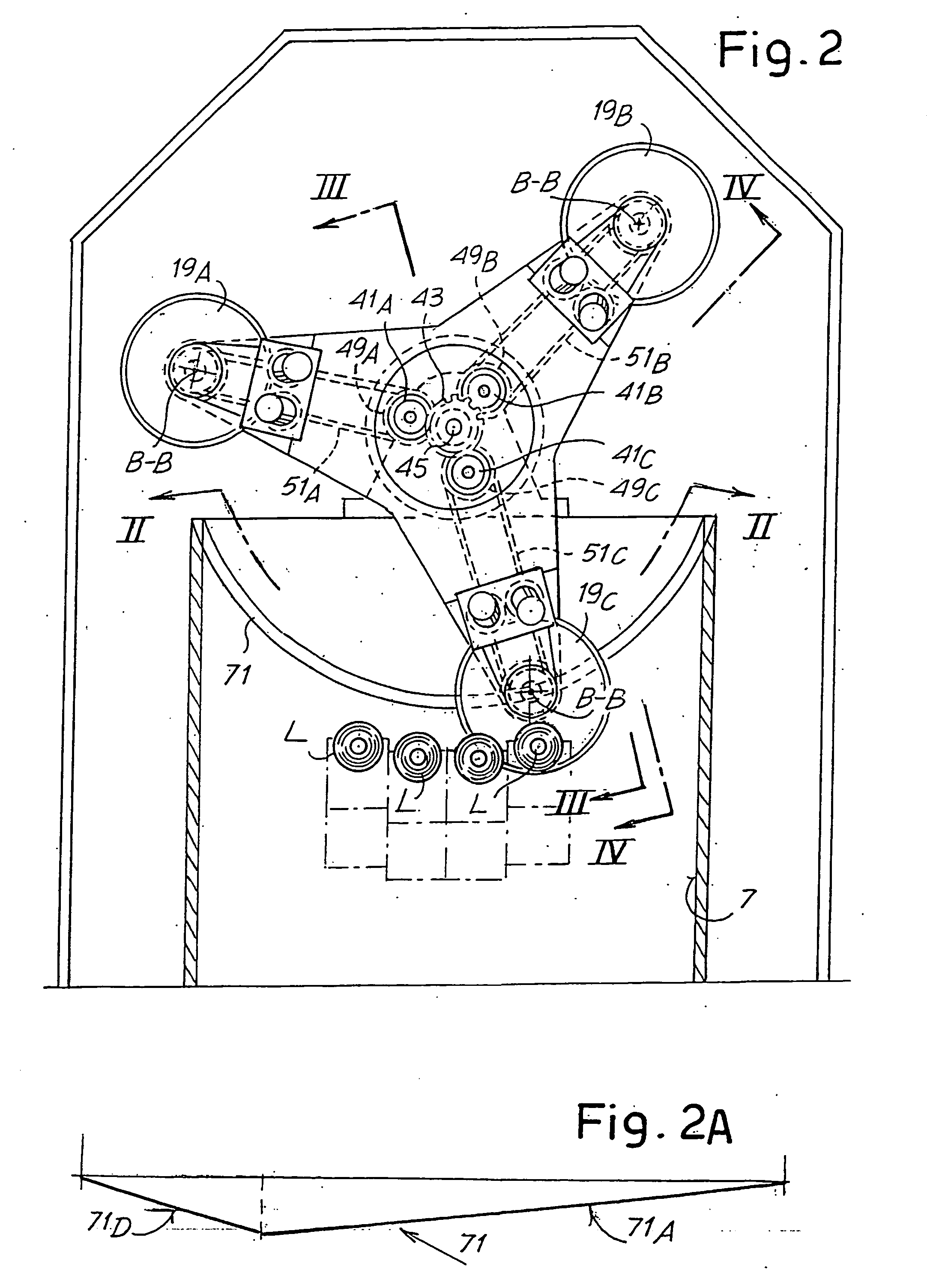
[0042] With reference to the FIGS. 2 and 3, which show the machine according to the invention, these show how the rotating element 17, drawn in rotation by the hub 17A, has three toothed wheels inside it, disposed at 120° from one another around the axis A-A, indicated with 41A, 41B and 41C. Said wheels mesh with a central toothed wheel 43 keyed onto a shaft 45, which receives motion from the motor 25 through the belt 27.

[0043] The toothed wheels 41A, 41B and 41C are keyed onto respective spindles 47A, 47B and 47C onto which toothed pulleys 49A, 49B and 49C are in turn keyed. Each of the toothed pulleys 49A, 49B, 49C transmits the motion supplied by the motor 25, through toothed belts 51A, 51B, 51C, to the rotating disk-shaped cutting blades 19A, 19B and 19C.

[0044] As can be seen in the detail in FIG. 5 for the blade 19C and in the detail in FIG. 6 for the blade 19A, the toothed belt 51A, 51B, 51C transmits motion to a toothed pulley 53A, 53B, 53C keyed onto an axis 55A, 55B and 55...

second embodiment

[0062]FIG. 4 shows a side view of the rotating element 17 in the cutting machine according to the invention. The same numbers indicated the same or equivalent parts to those of the previous embodiment. The variation lies in the different way in which alternate movement is transmitted to the three disk-shaped blades 19A, 19B, 19C supported by the rotating element 17. While in the previous case each disk-shaped blade was supported by a sleeve equipped with a feeler 67A, 67B or 67C cooperating with a single annular cam 71, in this case the sleeves that carry the shafts 55A, 55B and 55C of the blades 19A, 19B and 19C cooperate with three respective rockers 121A, 121B and 121C hinged in X to the rotating element 17 and bearing (at the opposite end from the one cooperating with the supporting sleeves of the rotating disk-shaped blades 19A, 19B, 19C) small wheels 123A, 123B and 123C cooperating with an annular cam 125 disposed coaxially around the axis A-A of rotation of the rotating eleme...


PUM

PropertyMeasurementUnit
Electric chargeaaaaaaaaaa
Currentaaaaaaaaaa
Digital informationaaaaaaaaaa

Abstract

The cutting machine comprises at least one path for the products to be cut (L); at least one device (3, 5, 9) for feed of the products along said path, according to a direction of feed (fL); an element (17) rotating around a main axis of rotation (A-A); on said rotating element, at least one disk-shaped blade (19A, 19B, 19C) rotating around its own axis of rotation (B-B), said blade being provided with alternate translatory motion, substantially parallel to the direction of feed. The disk-shaped blades moves axially in relation to the rotating element during rotation of said rotating element. Moreover, the translatory movement of the disk-shaped blade is controlled so that it moves in the same direction as the direction of feed of the products to be cut when the blade is engaged in said products to follow the feed of the products during cutting. Motion in the opposite direction to the direction of feed of the products is imparted on the blade in a period of time in which the blade is disengaged from said products.

Description

TECHNICAL FIELD [0001] The present invention relates to a cutting machine for cutting elongated products, in particular for cutting logs of wound web material to obtain small rolls with limited axial dimensions in relation to the length of the initial logs. STATE OF THE ART [0002] Cutting machines are commonly utilized in the paper converting industry to produce small rolls from logs of wound paper, with a multiple axial length in relation to the axial length of the finished product, corresponding to the axial dimension of the reels of paper supplied by paper mills. [0003] Cutting machines commonly used to cut logs of paper or other wound web material are provided with an element rotating around an axis usually parallel to the direction of feed of the logs to be cut. These are fed along one or more channels parallel to one another to be subjected to the action of a rotating disk-shaped cutting blade carried by the rotating element. The disk-shaped blade rotates around an axis in tur...

Claims


Application Information

Patent Timeline
IPC IPC(8): B23D19/00A24C5/00B26D3/16B26D5/22B26D7/12
CPCB26D3/16B26D5/22B26D7/12B26D2210/11Y10T83/7684
Inventor CHIOCCHETTI, MARIO GIONIGELLI, MAURO
Owner FABIO PERINI SPA
Why Eureka
Try Eureka