Multi-station press machine

Inactive Publication Date: 2006-07-27
KINGSLEY CARDS
8 Cites 1 Cited by

AI-Extracted Technical Summary

Problems solved by technology

Firstly, the mechanical parts of the machine are complex, and therefore costly to manufacture.
Secondly, the machine is difficult to adapt to short runs of different types of card, because the linkages for the mechanical press levers have to be individually adjusted to apply the correct pressure for the desired process, and adjustment is not straightforward.
The adjustment requires skill to ensure that the pressu...

Method used

[0021] The underside of the fixed head plate 7 carries a support for the die or foiling tool 9 such that the tool can be slid into and out of position easily to permit a rapid changeover from one tool to another. In use, foil passes from a supply reel carried by a first horizontal support 11 down one side of the head plate 7, under the face of the die or tool 9 and back up the other side of the head plate 7, the waste material being wound on to a collection reel 10 mounted on the carrier 8.
[0023] The modular nature of the machine means that it can be readily adapted to carry out different finishing processes, and in particular different combinations of processes, such as die stamping, embossing and foiling. Work pieces passed successively from one station to the next, being transported into, between, and out of the workstations by a conveyor 12 mounted between the slidable plates 5 and the head plates 7 inwardly of the pillars 6. The conveyor 12 is described hereinafter in greater detail with reference to FIGS. 4 and 5.
[0024] Referring to FIGS. 4 and 5, the conveyor 12 consists of three modular units 12a, 12b and 12c, mounted so as to overlap to provide continuous conveyance of the workpieces 13 from the input table 14 through the three workstations to the output table 15. Each of the units 12 consists of a track containing an endless belt mounted over support wheels within the track and driven by an electric motor 16 mounted at one end of the track. The...

Benefits of technology

[0013] The control means is preferably linked to transducers detecting the instantaneous positions of the conveying means ...

Abstract

A print-finishing press comprises a bed (5) for receiving a workpiece, a hydraulic ram mounted to effect relative movement between the bed and a press tool (9), and pressure control means for selectively pre-setting the hydraulic pressure applied to the ram to any of a number of predetermined levels.

Application Domain

Mechanical working/deformationRotary presses +2

Technology Topic

Machine pressHydraulic ram +6

Image

  • Multi-station press machine
  • Multi-station press machine
  • Multi-station press machine

Examples

  • Experimental program(1)

Example

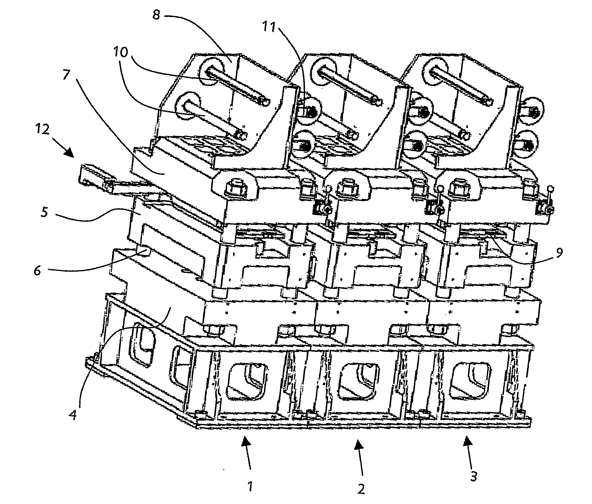
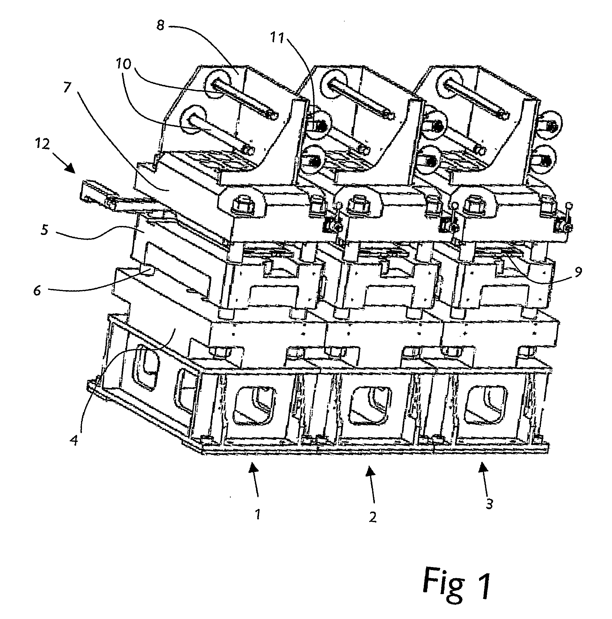
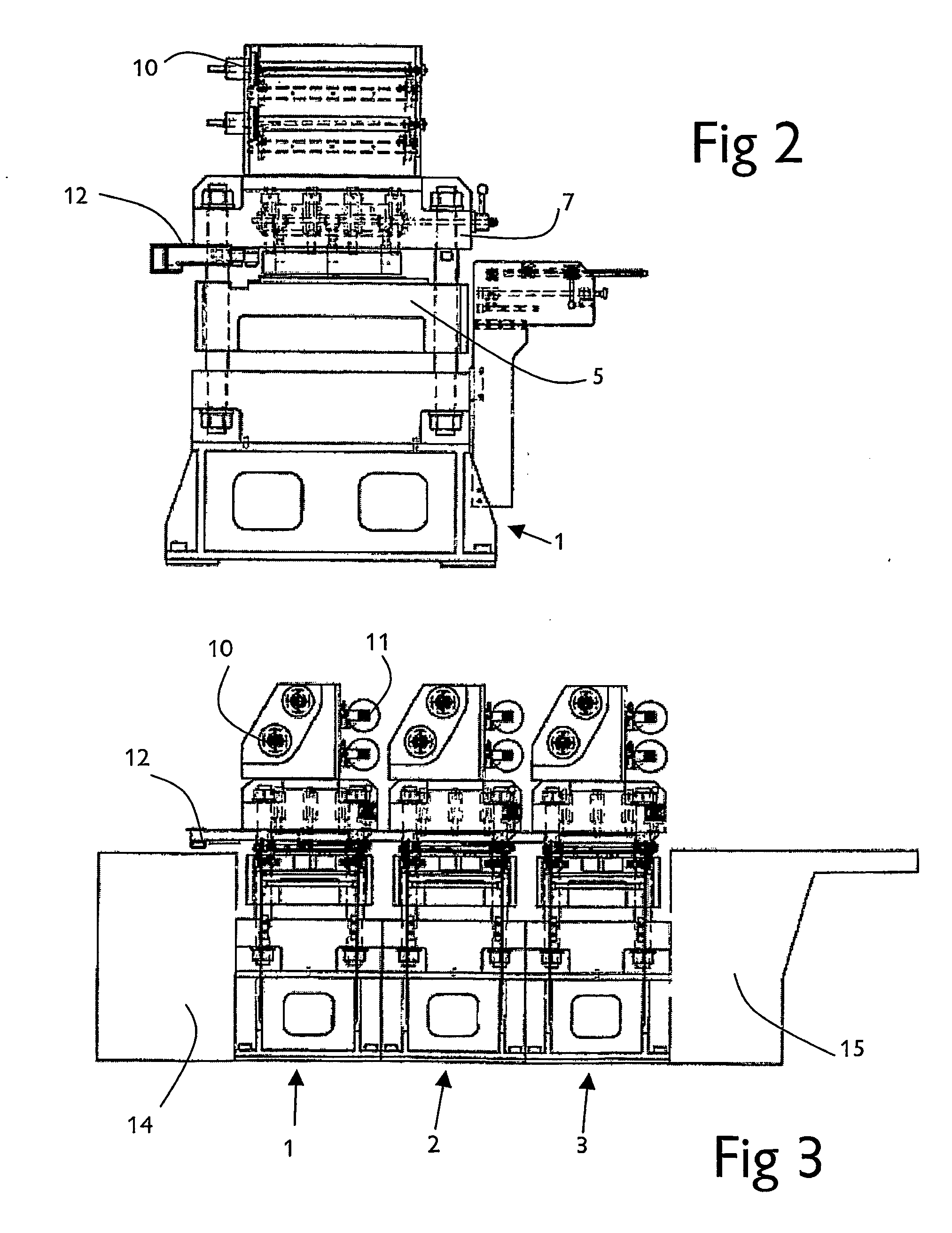
[0020] Referring first to FIGS. 1 to 3, a three-station print finishing press comprises three substantially identical modular units 1, 2 and 3, each consisting of a base frame 4 containing a hydraulic ram (not shown) mounted vertically so as to act on a press bed plate 5 which is slidably mounted on four vertical pillars 6 extending upwardly from the base frame 4. The pillars 6 carry between them at their upper ends a fixed head plate 7 on which is mounted a carrier 8 to support reels of foil for use in a hot foiling process.
[0021] The underside of the fixed head plate 7 carries a support for the die or foiling tool 9 such that the tool can be slid into and out of position easily to permit a rapid changeover from one tool to another. In use, foil passes from a supply reel carried by a first horizontal support 11 down one side of the head plate 7, under the face of the die or tool 9 and back up the other side of the head plate 7, the waste material being wound on to a collection reel 10 mounted on the carrier 8.
[0022] It will be seen that the pressing action is carried out by extending the ram upwardly to carry with it the slidable press bed plate 5 carry on the workpiece and urging the plate 5 against the die 9 mounted beneath the head plate 7.
[0023] The modular nature of the machine means that it can be readily adapted to carry out different finishing processes, and in particular different combinations of processes, such as die stamping, embossing and foiling. Work pieces passed successively from one station to the next, being transported into, between, and out of the workstations by a conveyor 12 mounted between the slidable plates 5 and the head plates 7 inwardly of the pillars 6. The conveyor 12 is described hereinafter in greater detail with reference to FIGS. 4 and 5.
[0024] Referring to FIGS. 4 and 5, the conveyor 12 consists of three modular units 12a, 12b and 12c, mounted so as to overlap to provide continuous conveyance of the workpieces 13 from the input table 14 through the three workstations to the output table 15. Each of the units 12 consists of a track containing an endless belt mounted over support wheels within the track and driven by an electric motor 16 mounted at one end of the track. The motor will typically be a stepper motor to permit precise positional control. Pneumatically operated grippers 17, which can be seen more clearly from FIG. 5, are mounted at uniform intervals along the belt, units 12a and 12b having three grippers each, while the third unit 12c has only one gripper. The grippers are arranged to extend and retract transversely of the direction of motion of the belts and to be openable and closable to release and grip the workpieces.
[0025] It will be seen from FIG. 5 that the grippers are arranged to carry the card workpieces 13 by gripping only a small portion in the region of the card which is not to be finished by embossing, cutting or foiling. In conventional machines, an edge portion of the workpiece has to be left free of printing, embossing etc to permit it to be gripped by the conveying devices. This means that the edge portion has subsequently to be trimmed off, involving another operation, and so slowing production, and also generating waste. This advantage is achieved with single-fold cards or with double-folded cards. In FIG. 5, the printed/embossed/foiled areas are represented by hatching.
[0026] The modular construction of the machine, and the use of electrically driven belt positioners in the conveyors, enables the machine to be readily controlled by means of a computer control system, offering a high degree of flexibility in carrying out the finishing operations and moving the workpieces through the machine. In consequence, a high throughput can be achieved by the machines, and the machines can be readily adapted to process relatively short runs of print finishing of different types. The use of a hydraulic ram to control the pressing operation means that the pressure applied to the workpiece, and indeed the pattern of pressure applied, can be precisely controlled according to the materials being used. Thus, for example, an embossing action might require a different peak pressure, and different pressure profile, to a hot foiling operation. It will be understood that the foiling operation may require each, and this will be achieved by heating the foiling tool or die electrically.

PUM

PropertyMeasurementUnit
Pressure

Description & Claims & Application Information

We can also present the details of the Description, Claims and Application information to help users get a comprehensive understanding of the technical details of the patent, such as background art, summary of invention, brief description of drawings, description of embodiments, and other original content. On the other hand, users can also determine the specific scope of protection of the technology through the list of claims; as well as understand the changes in the life cycle of the technology with the presentation of the patent timeline. Login to view more.
Why Eureka
Try Eureka