Sea-based hydrogen-oxygen generation system

a hydrogen-oxygen generation and sea-based technology, applied in the direction of vessel auxiliary drives, special-purpose vessels, vessel construction, etc., can solve the problems of limited political opposition, and high cost of energy generation at sea, so as to reduce objections.

a hydrogen-oxygen generation and sea-based technology, applied in the direction of vessel auxiliary drives, special-purpose vessels, vessel construction, etc., can solve the problems of limited political opposition, and high cost of energy generation at sea, so as to reduce objections.

US20060162642A1Inactive Publication Date: 2006-07-27MORSE ARTHUR +1

Image

  • Sea-based hydrogen-oxygen generation system
  • Sea-based hydrogen-oxygen generation system
  • Sea-based hydrogen-oxygen generation system

Examples


Embodiment Construction

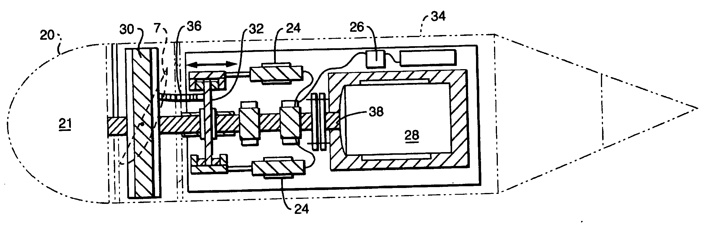
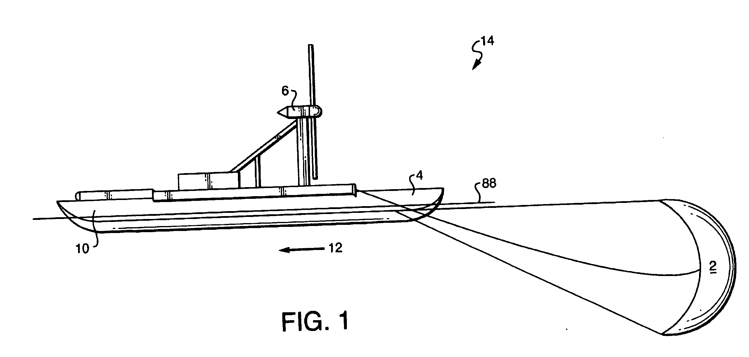
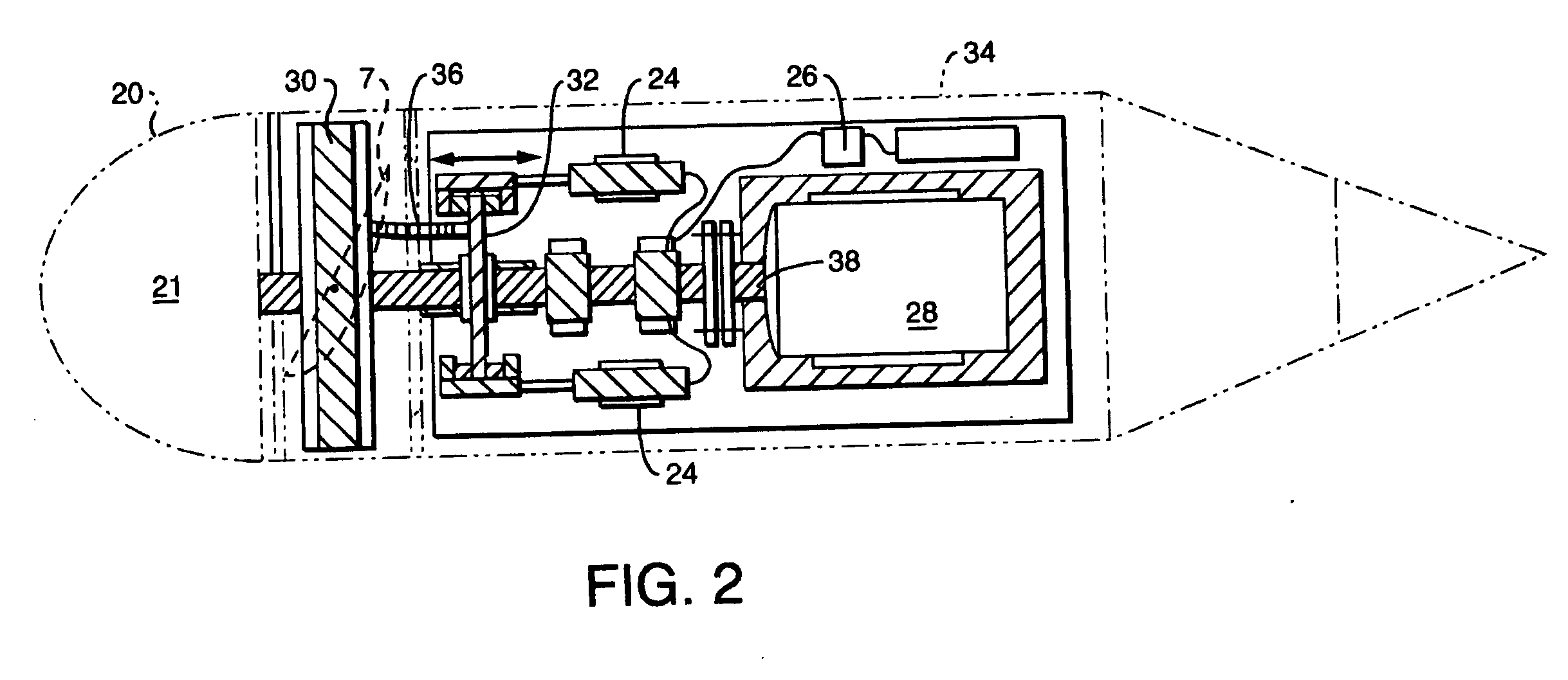
[0056] The present system utilizes a number of collection vessels each of which has on-board wind or wave power devices to convert the energy contained in the wind and waves to an electrical current which is then used to create hydrogen and oxygen from water by means of electrolysis. The collection vessels are of two distinct types: the wind-based collection vessels use the power of the wind to turn a wind turbine, which is coupled to an electric generator; the wave-based collection system uses the energy stored in waves to perform the same function.

[0057] The present wind-based collection system utilizes 19th century technology, using a turbine with many blades on a single turbine rotor. In this way it maximizes the amount of blade surface area exposed to the wind to create increased torque, which, in turn, increases the output of the generator used for electrolysis. Any combination of voltage and current will cause the electrolysis process to work. Therefore, the main area of con...


PUM


Abstract

A method for generation of gasses contained in a salt solution in accomplished by disposing automated, floating wave power collection vessels in waters distant from shore, the vessels navigating within one or more predetermined geographic zones, having suitable wave conditions for such operation. The wave power devices generating electricity and the gasses are extracted from the salt solution by electrolysis. Automated storage vessels are used as shuttles to deliver the gasses to shore facilities.

Description

[0001] This application is a continuation in part of co-pending U.S. application Ser. No. 10 / 709,744 filed on May 26, 2004.BACKGROUND OF THE INVENTION [0002] The present invention is a system and method for using wave and wind power for the generation of hydrogen and oxygen. In its simplest form the wind is used to rotate a wind turbine, which is attached to an electric generator, and the waves are used to rotate the blades of an impeller driven by the water pressure created by waves. The electricity produced by the generator is then used to power an electrolysis subsystem, which produces hydrogen and oxygen from the water in the electrolysis salt bath. [0003] The novelty in the present system arises from the fact that both the wind turbines and the wave power generators are located on collection vessels at sea, configured for this purpose. The vessels can be disposed out of the sight of land, which avoids the political problems attendant to the location of wind farms in proximity t...

Claims


Application Information

Patent Timeline
27 Jul 2006
Publication
US20060162642A1
IPC
B63B35/00; B63B17/00; B63B21/48; B63B38/00; F03D9/02
CPC
B63B21/48; B63B38/00; B63J3/04; B63J2003/046; F03D9/008; F03D9/02; F05B2210/16; Y02E10/72
Inventors
MORSE, ARTHUR