"Countdown Timer" automatic water limiting supply shut off safety valve flo-control system

a technology of automatic water limiting supply and safety valve, which is applied in the direction of valve operating means/releasing devices, mechanical equipment, transportation and packaging, etc., can solve the problems of many external moving parts subject to mechanical failure, waste of water, and overflow, and achieves the effect of preventing siphon and backflow, cost-effective, and easy installation

Inactive Publication Date: 2006-07-27
ARIGONI JOHN HENRY
View PDF4 Cites 21 Cited by
  • Summary
  • Abstract
  • Description
  • Claims
  • Application Information

AI Technical Summary

Problems solved by technology

Typically these toilet fill valves work fairly well but have several drawbacks that lead to wasting of water, overflow, and leaks.
These drawbacks result in a myriad of problems from wells running out of water, dirt being introduced into the water lines from low water levels in shallow wells, and septic system failure, to high water and sewage bills for those on public water supply and sewage systems to water damage to the floor of a bathroom, and ceilings and walls of a downstairs room to remediation of mold and mildew.
Though this device can effectively cause shut off, it tends to have many external moving parts subject to mechanical failure and also uses most of the toilet tank area and servicing as well as installation require more intensive labor and increased expense.
Both of the foregoing devices utilize a large portion of the toilet tank area to the right of the flapper valve causing access to the flapper to be flanked on all sides and tends to limit service space for repairs, causing repairs to be costly and labor intensive.
Though both Rise controls address stopping automatic function of the flapper and limiting the flappers movement they do not address wasting of water when the flapper becomes defective by means of blowout, tear or just ordinary wear of the seal, the results of which could lead to a continuous loss of water to the sewer or overflow and water damage.
This device though it appears to be quite functional also renders much the same results as the Weir devices utilizing or cluttering tank space hindering and causing labor intensive costly service when repairing or replacing the flapper or primary float valve.
The secondary float fill valve is also still subject to fail in much the same way as the primary float fill valve.
While this system would effectively shut off the flow of water it is possible that with the rotating movement of the float assembly, it could eventually cause leakage and overflow from wear due to excessive movement.
Most of these devices work fairly well shutting off the water, while addressing anti-siphoning of water but do not adequately address backflow prevention, wasting of water if the float fails to be elevated by the water or lack thereof, and or overflow of the bowl or a leaky gasket between tank and toilet.
The major drawbacks of such devices are that they require regular and periodical battery maintenance and replacement as well as regular cleaning of the sensor devices that appear as necessary clutter and are actually in the way of cleaning the bowl and or the floor.
Additionally, the cleaning of the sensors and the chemicals used, both cleansers and antibacterial toilet additives can cause premature failure.
Although the sensor in the bowl will effectively stop overflow of the bowl or bowl in households with children who might lose a toy or otherwise plug the bowl, a floor sensor could present a problem with flushing where bath water is accidentally splashed on it or if a child accidentally misses the bowl and wets the sensor.
Electronic valve systems such as the above generally utilize a normally open solenoid valve so the batteries will last a long time if the valve is not triggered shut by a sensor; however, if the valve is triggered shut in the case of a flapper leak the batteries would not last very long which would in short time lead to water running to the sewer or worse yet water damage if the bowl was plugged.
Although this device is impressive it has the possibility of lockup of the drive system.
Additionally, this ratchet cam system does not address the ability to adjust the volume of water metered so a 3.5 gallon valve will not service the 1.5 gallon tank of a newer toilet or vise versa.
In other words one size does not fit all due to the arrangement of the fixed setting or position of notches in the cam and the ratcheting mechanism.

Method used


Image

  • "Countdown Timer" automatic water limiting supply shut off safety valve flo-control system
  • "Countdown Timer" automatic water limiting supply shut off safety valve flo-control system
  • "Countdown Timer" automatic water limiting supply shut off safety valve flo-control system

Examples


Embodiment Construction

[0040] The following description is provided to enable any person skilled in the art to make and use the invention and sets forth the best modes contemplated by the inventor for those so skilled to do so.

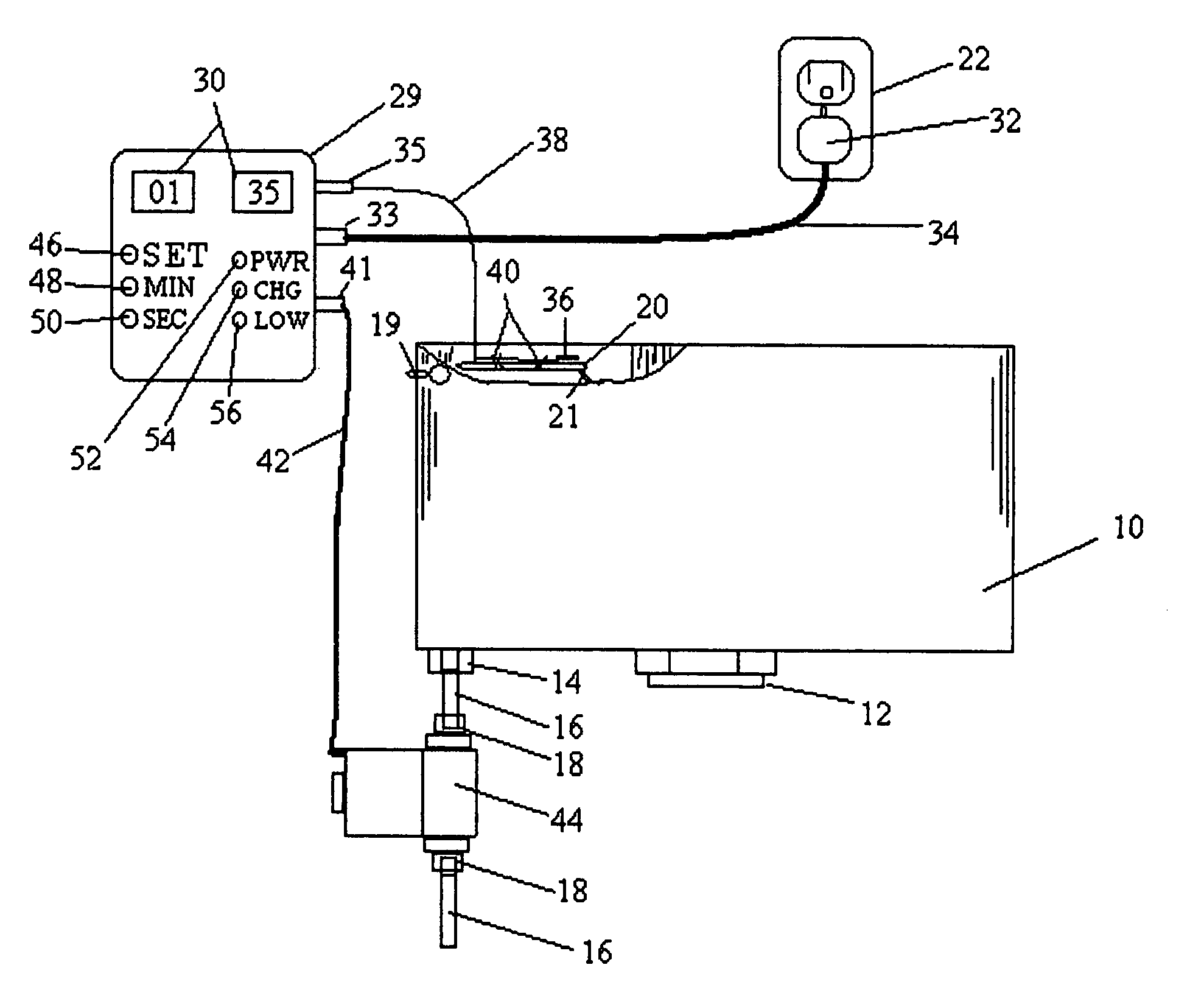
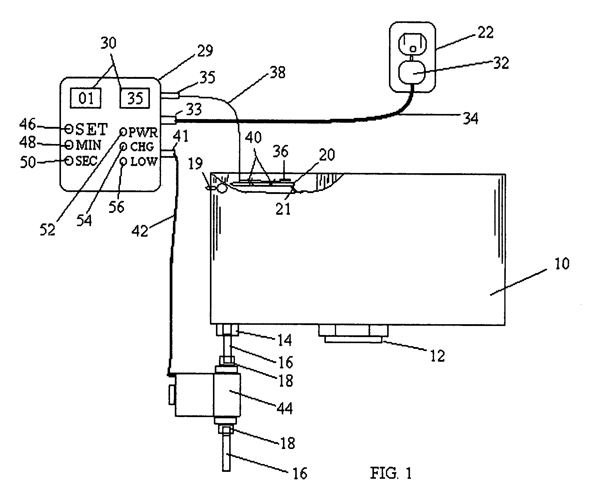
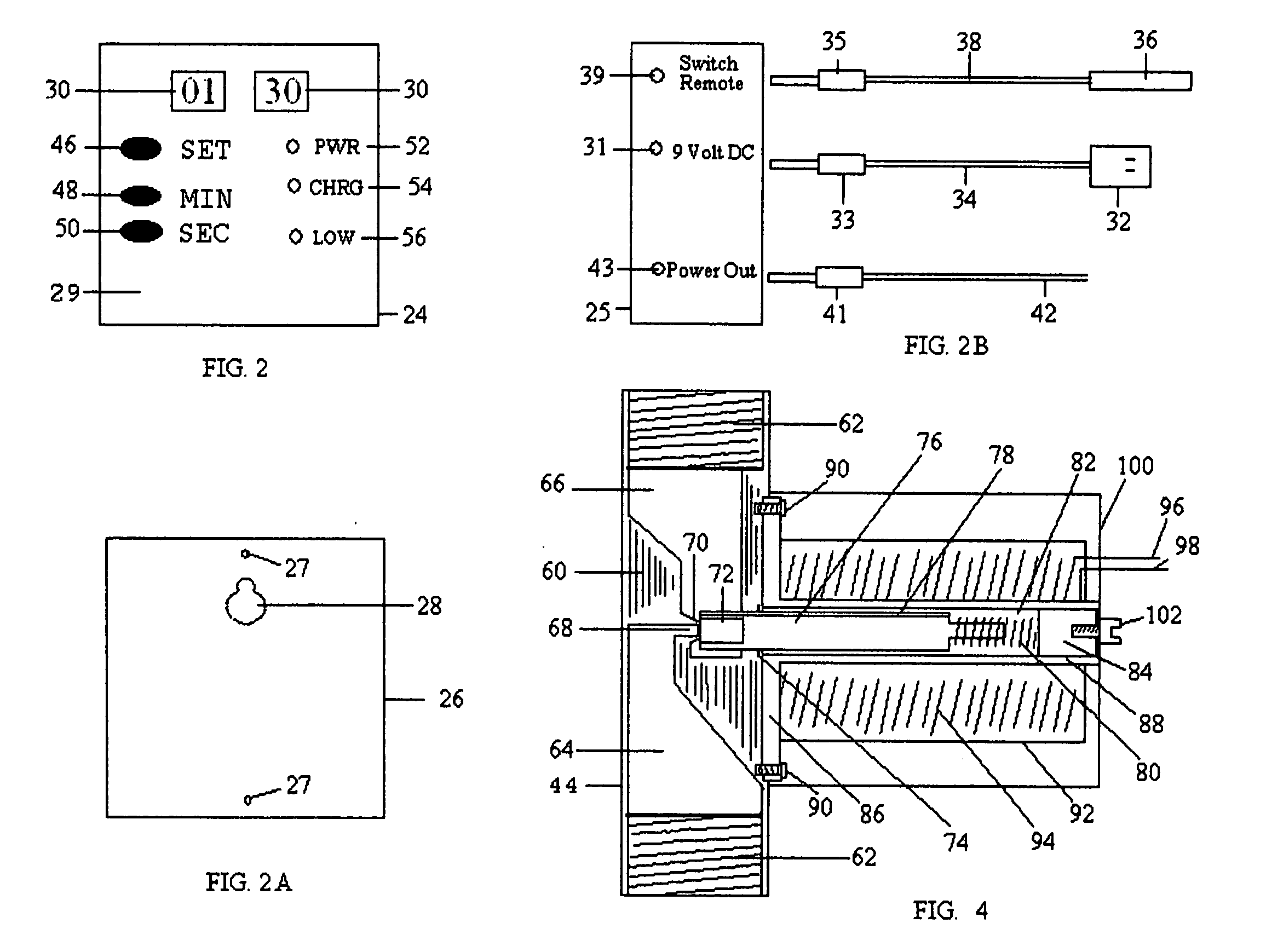
[0041]FIG. 1 is a front view of a conventional toilet tank 10, of the type universally found in most homes in the United States and North America, which is fitted with a Countdown Timer 29, and a Solenoid Safety Valve 44, in accordance with the present invention. In the conventional home toilet, a ball cock assembly comprising a float arm, and float ball is mounted at the upper end of a water tube for closing an inlet valve via a mechanical linkage when the tank is filled to a predetermined level. In the present invention a float valve assembly is left unchanged being mounted to the tank in its usual fashion.

[0042] The illustrated toilet tank comprises a toilet tank 10 with a float valve inlet 14, extending through the left rear bottom of the tank 10. Water supply is introduced by...


PUM


Abstract

An electronically controlled electro-mechanical device designed to limit a finite amount of water per flush to a tank reservoir of the common household toilet, or tank-less toilet or urinal, providing positive shutoff of water flow and anti-siphon backflow prevention. The toilet is flushed, the flush lever activates an attached tilt switch, the tilt switch actuates the countdown timer by means of electrical linkage, the countdown timer in turn activates the solenoid valve by means of electrical connection. The water enters the solenoid valve, passing through the valve and on to the float valve mounted to the toilet tank for fill up. The Countdown timer counts down from the full minutes and seconds set to 00:00 and shuts off the solenoid valve and ultimately the flow of water. The Countdown timer then resets itself to the time set in memory for the next flush operation. A float eliminator may be affixed to the toilet tank replacing the float valve, then connected to the solenoid valve. For the purpose of adjusting the volume of water per flush the Countdown timer can be programmed from 00:00 minutes and seconds to 99 minutes and 55 seconds. The average toilet will need approximately 2 minutes. It is suggested that the user flush and time his toilet prior to installation of the electro-mechanical solenoid valve unit and add five seconds to assure the proper volume of water per flush.

Description

[0001] I, claim priority filing date of Jan. 25, 2005 of provisional Application No. 60 / 646,853STATEMENT REGARDING FEDERALLY SPONSORED RESEARCH OR DEVELOPMENT [0002] Not Applicable REFERENCE TO SEQUENCE LISTING, A TABLE, OR A COMPUTER PROGRAM LISTING COMPACT DISC APPENDIX [0003] Not Applicable BACKGROUND FIELD OF INVENTION Current U.S. Class: 4 / 415: 4 / 366; 137 / 436; 210 / 170; 713 / 322 Intern'l Class: EO3D 001 / 00; C02F 003 / 02; G06F 001 / 04 REFERENCES CITED U.S. Patent Documents U.S. Pat. No. 6,903,766 Jun. 7, 2005 Silverbrook, et al. . . . 348 / 211.4; 348 / 333.06; 348 / 207.2; 396 / 264 U.S. Pat. No. 6,989,721 May 24, 2005 Schmidt . . . 713 / 322; 713 / 501; 713 / 600; 455 / 205; 455 / 502 U.S. Pat. No. 6,178,569 Jan. 30, 2001 Quintana . . . 4 / 427; 4 / 406; 73 / 304C; 137 / 392; 137 / 558; 340 / 620 U.S. Pat. No. 5,752,281 May 19, 1998 Conner . . . 4 / 427; 4 / 415 U.S. Pat. No. 5,524,299 Jun. 11, 1996 Dalfino . . . 4 / 415, 4 / 366; 137 / 410 U.S. Pat. No. 5,440,756 Aug. 15, 1995 Weir . . . 4 / 415; 137 / 400 U.S. P...

Claims


Application Information

Patent Timeline
Patent Type & Authority Applications(United States)
IPC IPC(8): F16K31/48
CPCE03D5/10Y10T137/86397Y10T137/86389
Inventor ARIGONI, JOHN HENRY
Owner ARIGONI JOHN HENRY
Why Eureka
Try Eureka