
Hybrid power supply module

Inactive Publication Date: 2006-07-27
AIRTRAX
View PDF0 Cites 66 Cited by
  • Summary
  • Abstract
  • Description
  • Claims
  • Application Information

AI Technical Summary

Benefits of technology

[0016] By being interchangeable with the battery in terms of form, fit, electrical interface and electrical power characteristics, this invention provides a simple and inexpensive means for converting existing battery powered mobile machinery, such as a forklift, to hybrid power with a minimum of host vehicle modification. This conversion will enable a battery powered electric forklift or other machine to operate on gaseous or liquid fossil fuels where such fuels are permissible, while retaining the ability to function on battery power alone in areas where acoustic, thermal, and gaseous emissions are not desired.
[0017] By being interchangeable with a conventional battery, this invention permits the vehicle to be converted back to all battery power when fossil fuel capabilities are not useful, thus providing the ability to inexpensively increase the machine endurance.
[0018] Another objective of this invention is to provide a means by which a machine such as a forklift can be rapidly reconfigured between conventional battery only and combined battery and fuel cell or internal combustion engine power.
[0020] Another objective of this invention is to provide an energy module that can enable on-the-fly change over of power supply so that a fork lift or other mobile machine can operate without pollution in a factory wherein workers are employed and revert back to a warehouse using internal combustion provided power without stopping to make physical changes to the vehicle.

Problems solved by technology

This optimization of vehicle system designs around the power source makes converting motorized vehicles or machinery from one power source to another very difficult and expensive.
For example, battery powered systems generally have low gaseous and thermal emissions but are disadvantageously heavy, have limited operating range and require an extended period of downtime to recharge.
Fossil fuel powered systems generally have high power density and less weight than battery powered systems, but disadvantageously generate gaseous, thermal, and auditory emissions.
Concepts for removable power supplies described above either do not permit a change over from one energy source to another, or require additional structure and mechanisms necessary for both energy sources.
Removable power supplies which do not permit switching between electrochemical and fossil fuel energy sources necessarily limit the vehicle applications as discussed above.
Vehicles that require structure for both electrochemical and fossil fuel energy sources will necessarily be heavier, more costly and less reliable.
Also, energy module designs that require special structural and mechanical interfaces with the vehicle necessarily mean that converting a host vehicle from one type of power source to the other will require expensive, time-consuming and complex modifications.
These shortcomings have added to the cost of converting vehicles to hybrid-power sources, thus contributing to the limited commercial successes of hybrid-powered vehicles and hybrid-power conversions of existing vehicles.

Method used


Image

  • Hybrid power supply module
  • Hybrid power supply module
  • Hybrid power supply module

Examples


Embodiment Construction

[0027] The drawings presented are for the purpose of illustrating present embodiments of the invention only and not for the purpose of limiting the same.

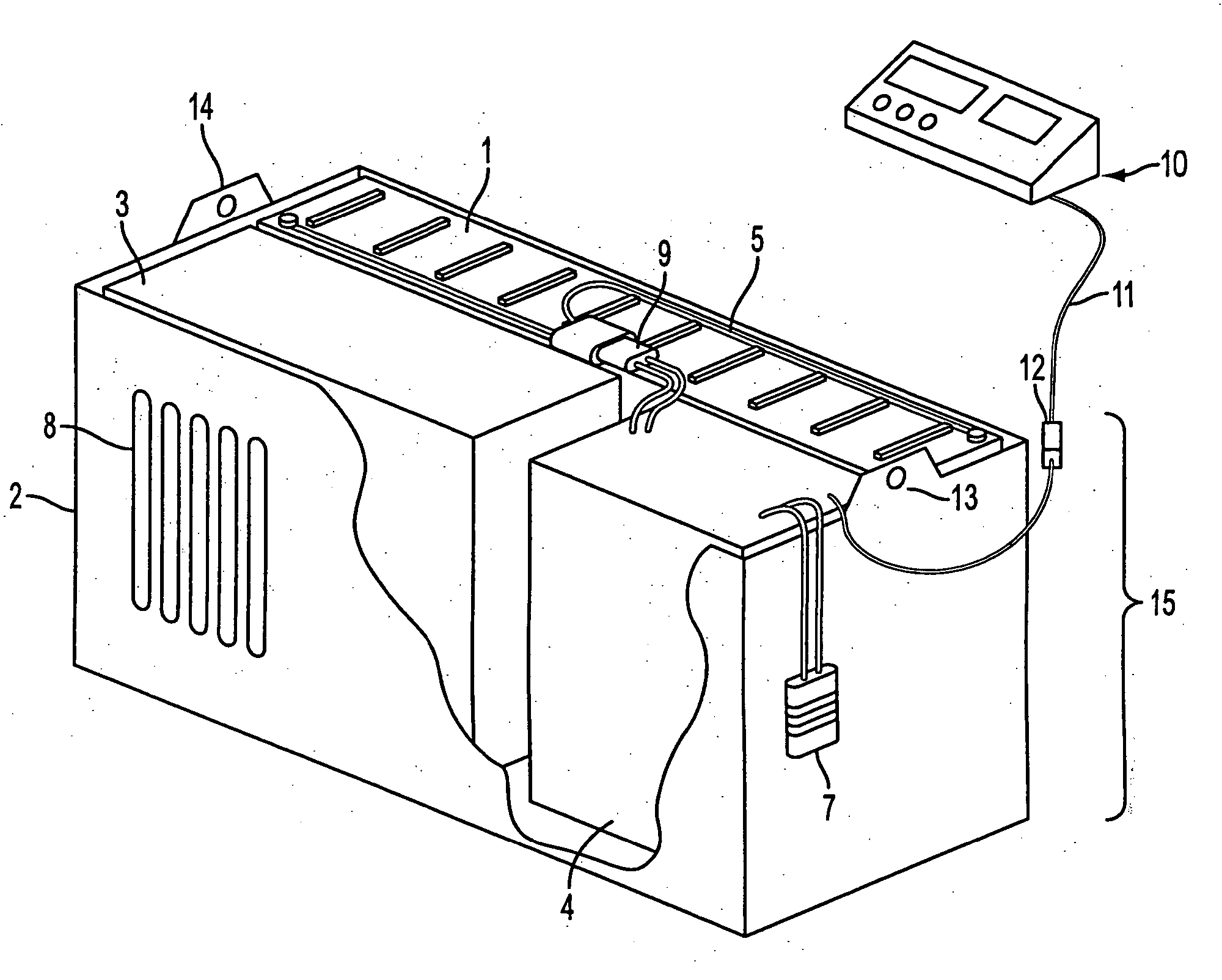
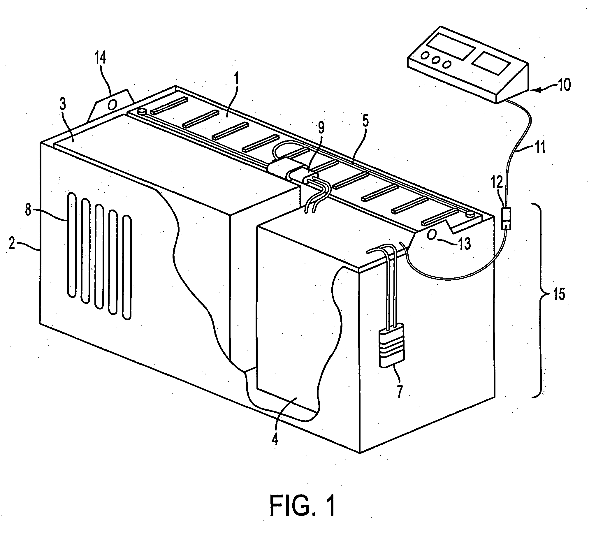
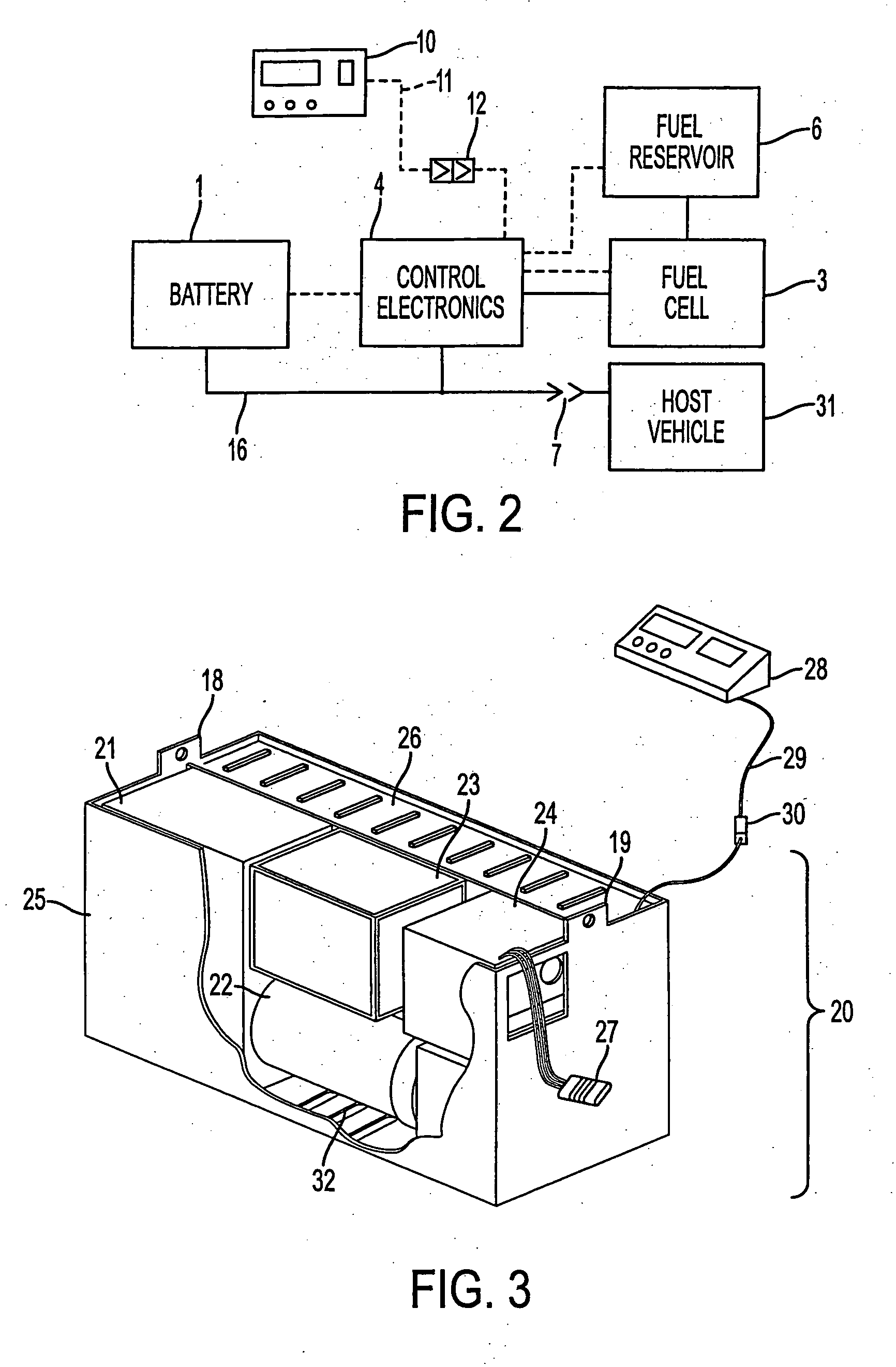
[0028] The first preferred embodiment of the invention is presented as FIG. 1 and includes the hybrid power supply module 15. The hybrid power supply module 15 includes a housing 2. Portions of the exterior surfaces of the housing 2 have been cut away in FIG. 1 to reveal interior details and exemplary arrangements of various components. Enclosed within the housing 2 are a battery 1, a fuel cell electrical power generator 3, and control electronics 4. The fuel cell electrical power generator 3 and control electronics 4 are electrically connected via cabling not shown. The battery 1 and control electronics 4 are electrically connected via cabling 5, which may include a plug disconnect 9 in series. The hybrid power supply module 15 is electrically connected to the host vehicle's power input via electrical cabling and a plug disconnect...


PUM


Abstract

An hybrid power supply module is disclosed. The hybrid power supply module is configured for placement in a battery compartment of an electrically powered machine and includes a housing that contains a battery, an electrical generator or fuel cell, and control electronics. The housing is sized to fit in the host electrically-powered machine's battery compartment. The battery and electrical power generator or fuel cell are coupled electrically to the electronic controls. A method of replacing a battery.in an electric powered machine with a renewable power source is also disclosed. The method includes uncoupling the battery from the machine, removing the battery from a battery compartment of the machine, placing the hybrid power supply module in the battery compartment, and coupling the hybrid power supply module to the machine.

Description

CROSS-REFERENCE TO RELATED APPLICATIONS [0001] U.S. application Ser. No. 09 / 056,109, filed Apr. 6, 1998. This application claims the benefit of priority from U.S. Provisional Application No. 60 / 197,391 filed Apr. 14, 2000, which is hereby incorporated by reference.STATEMENT OF GOVERNMENT INTEREST [0002] Not applicable. BACKGROUND OF THE INVENTION [0003] The present invention relates generally to power supplies and, more particularly, to a hybrid removable power supply module for a machine such as a forklift, a car, a truck or any motorized vehicle or other machines requiring a power source. [0004] Powered machinery, and particularly mobile machinery such as motorized vehicles, fork lifts, cars, trucks and vehicles using a regenerableable source of energy are generally designed to operate on either battery (e.g. rechargeable batteries) or fossil fuel power sources (e.g. internal combustion engine, turbine engine or fuel cell). While battery and fossil fuel powered mobile machinery ma...

Claims


Application Information

Patent Timeline
IPC IPC(8): B60L8/00B60K1/04B60K5/10B60K6/00B60K6/24B60K6/26B60K6/28B60K6/32B60K6/405B60L11/18B66F9/06B66F9/075H01M8/04H01M10/42H01M16/00H01M50/202
CPCB60K1/04B60K5/10B60K6/00B60K6/24B60K6/26B60K6/28B60K6/32B60K6/405B60L11/02B60L11/123B60L11/126B60L11/1861B60L11/1877B60L11/1879B60L11/1887B60L11/1896B60L2200/42B60L2250/16B60L2270/40B60W2710/06B60Y2200/15B66F9/06B66F9/07531B66F9/07572B66F9/07595H01M2/1016H01M8/04298H01M8/04365H01M8/04395H01M8/04567H01M8/04589H01M8/0491H01M8/04917H01M10/4257H01M16/003Y02E60/50Y02T10/6217Y02T10/6295Y02T10/7005Y02T10/7044Y02T10/705Y02T10/7077Y02T90/124Y02T90/34Y02P90/60B60L50/10B60L50/61B60L50/62B60L50/66B60L50/64B60L58/40B60L50/71B60L58/15Y02T10/62Y02T10/70Y02T10/7072Y02T90/40Y02E60/10H01M50/202Y02T90/12
Inventor HARRIS, DONALD B.AMICO, PETER
Owner AIRTRAX
Learn More