
Vibration and noise abatement pad

a technology of vibration and noise reduction, which is applied in the direction of machine supports, instruments, other domestic objects, etc., can solve the problems of not easy to break down in air or soil, discarded tires in piles of scrap or used tires are often worn to the point where reinforcing wires are exposed, and the disposal of scrap or used tires poses a serious threat to our environment, etc., to achieve efficient run-off and/or draining, and reduce noise and vibration

Inactive Publication Date: 2006-07-27
ATIRE TECH
View PDF27 Cites 14 Cited by
  • Summary
  • Abstract
  • Description
  • Claims
  • Application Information

AI Technical Summary

Benefits of technology

[0004] The invention provides a base pad for supporting mechanical machines and is configured such that it reduces the noise and vibration emanating from these machines. Additionally, the configuration of the pad in accordance with the present invention provides for the efficient run-off and / or draining of any moisture generated from under the machine unit.
[0005] In addition to saving the machine unit from damage caused by floor water, the inventive pad plays a vital role in extending the life of the unit since it reduces the vibration of the unit caused by its internal components. Furthermore, the inventive pad reduces the noise generated by the machine unit thus rendering the machine more amenable to various interior locations inside a home or office.
[0007] The pad in accordance with the present invention is molded and formed from 100% comminuted rubber tires. The overwhelming majority of the tires used in preparing these pads will come from waste dumps and recycle centers. As such, the use of these tires in the manufacture of the inventive pad in accordance with the present invention provides an extremely valuable use for a very undesirable waste product and as such eliminates a troublesome disposal problem and environmental nuisance.

Problems solved by technology

It is known that the disposal of scrap or used tires poses a serious threat to our environment.
Unlike other waste products, tires do not readily break down in air or soil.
Often, whole tires are simply piled onto vacant space within the dump, creating an eyesore.
As a further hazard, the discarded tires in these piles are often worn to the point where their reinforcing wires are exposed.
The exposed wire can injure persons handling the tires or children that attempt to climb the piles.
Chemical reactions between the tires, soil, and air trapped in the cavity can create sufficient heat to ignite the tires, creating a dangerous fire hazard.

Method used


Image

  • Vibration and noise abatement pad
  • Vibration and noise abatement pad
  • Vibration and noise abatement pad

Examples


Embodiment Construction

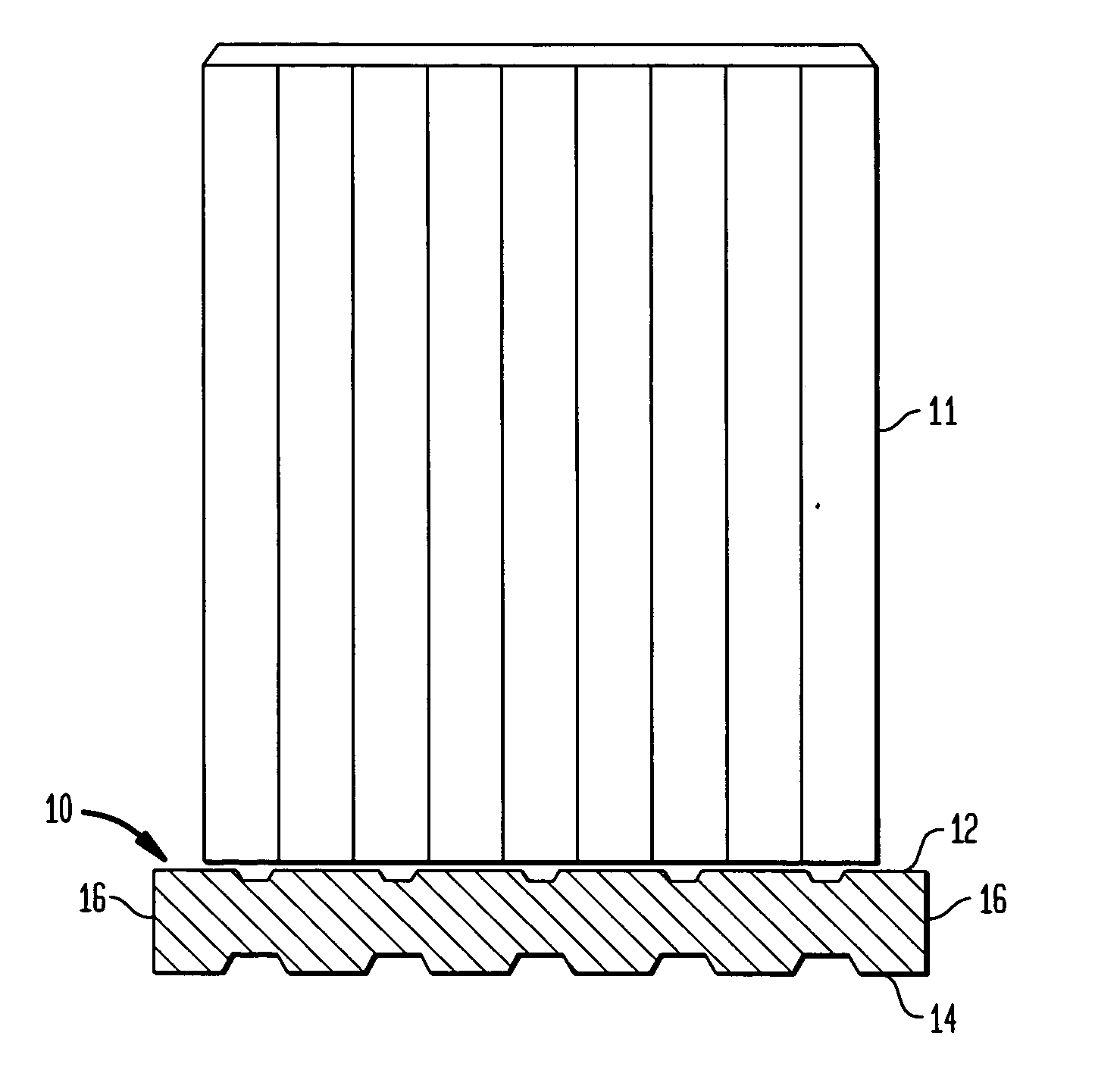
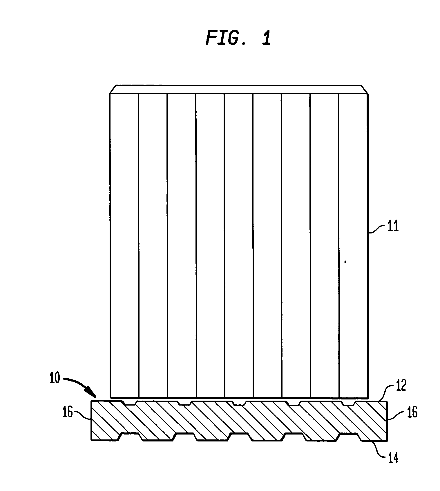
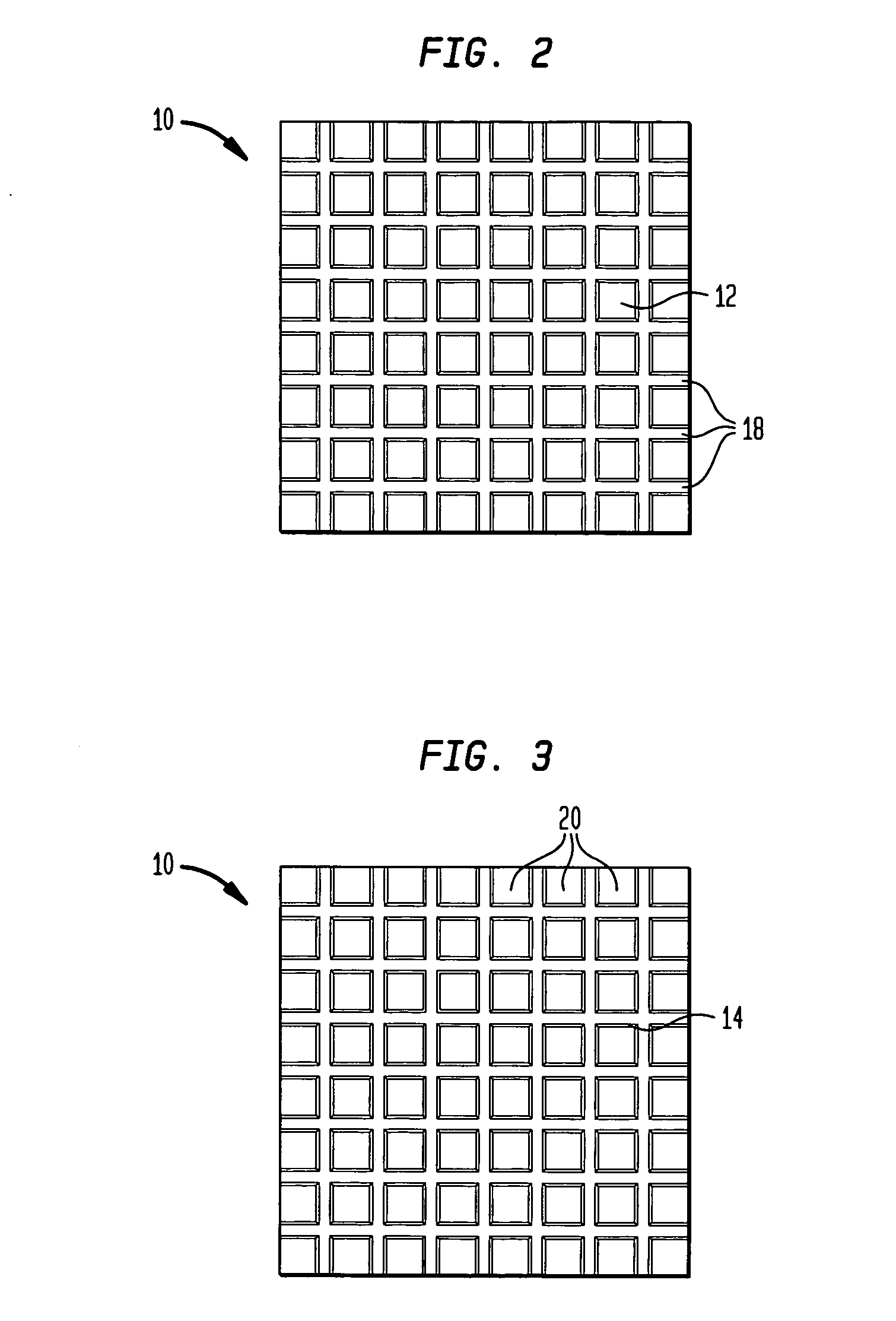
[0014] A monolithic pad 10 in accordance with one embodiment of the present invention is illustrated in FIGS. 1-3. Pad 10 has a top surface or upper side 12 and a lower surface or underside 14. A plurality of side surfaces 16 surround pad 10. FIG. 1 illustrates one embodiment of pad 10 with a machine unit 11 positioned on pad 10. In the embodiment illustrated in FIGS. 2 and 3, upper side 12 is provided having a “waffle-like” configuration. This “waffle-like” configuration is one comprising a plurality of channels 18 and indentations or pockets 20. Channels 18 on upper side 12 and underside 14 of pad 10 run parallel and perpendicular to each other and criss-cross or intersect one another on both upper side 12 and underside 14 of pad 10. Within the intersecting channels the indentations or pockets 20 are formed. Pockets 20 on underside 14 of pad 10 are generally configured to be deeper than pockets 20 on upper side 12 of pad 10; however the invention is not limited to this configurati...


PUM


Abstract

A base pad for supporting mechanical machines and equipment and which is configured such that it reduces the noise and vibration emanating from these machines. The pad is constructed entirely from shredded and comminuted rubber tires and is configured such that it provides for the efficient run-off and / or draining of any moisture generated from under the machine unit.

Description

FIELD OF THE INVENTION [0001] The present invention relates to a vibration and noise reducing pad. More specifically, the invention relates to a pad for positioning under a machine, such as for example, an air conditioner unit, a furnace, a heater, a refrigerator or washing and drying machines, and which supports the machine and absorbs the vibration and noise that emanate from the machine. BACKGROUND [0002] Heating, ventilation and air conditioning equipment are generally large machines with numerous mechanical parts on the inside such as compressors, condensers, heaters, evaporators, fans and motors to name just a few. The functioning of the parts inside these machines is generally loud and causes a significant amount of vibration. In many of these machines, vibration from a compressor, fan or motor often causes soldered joints to break and oftentimes to leak refrigerant of other fluids (some which may be caustic) which can lead to rapid degradation of components inside the unit. ...

Claims


Application Information

Patent Timeline
IPC IPC(8): G01M1/00
CPCF16F1/3737Y10T428/2457F16F2236/04F16F1/376
Inventor WILLIAMS, ROBERT F.WILLIAMS, ROBERT J.
Owner ATIRE TECH
Learn More