
Method and circuit arrangement for current measurement

Inactive Publication Date: 2006-07-27
SIEMENS AG
View PDF14 Cites 7 Cited by
  • Summary
  • Abstract
  • Description
  • Claims
  • Application Information

AI Technical Summary

Benefits of technology

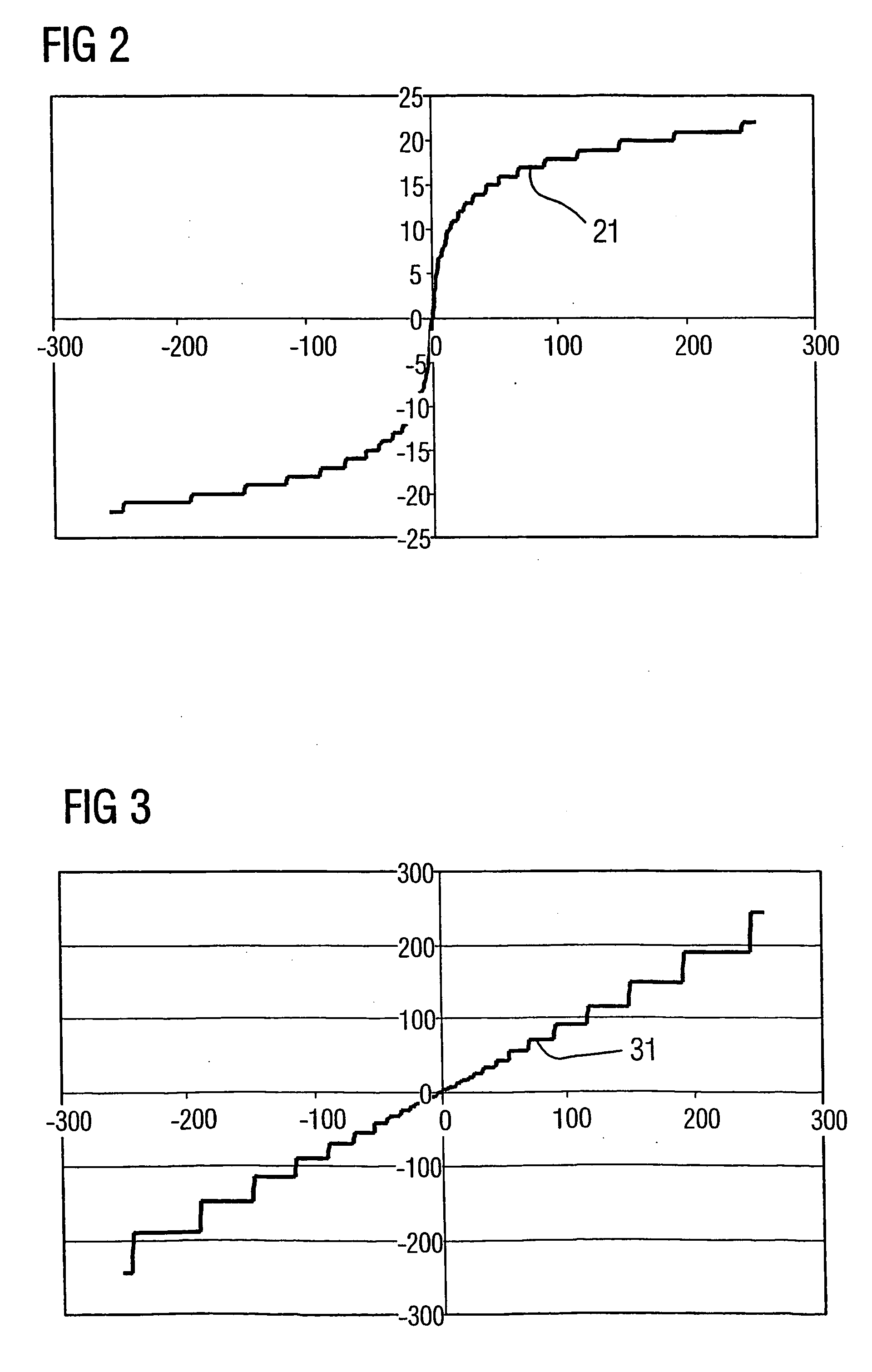
[0017] a) Dynamic response: the ADC is not implemented with a linear characteristic curve but rather with a rounded characteristic curve. As a result, the measurement signal is compressed and a smaller number of bits suffices for the same dynamic response. This method, which is known as compression, is thus intended to be advantageously applied to current measurement. Possible characteristic curves are logarithmic characteristic curves (with special handling of the zero point), which have the advantage of constant relative accuracy, i.e. errors relative to the measured value, or a root function, which affords the advantage of simple expansion by squaring, for example in a microcontroller.
[0021] At least one of the following advantages over the prior art may be achieved, in particular, with an embodiment of the invention:
[0022] a) High dynamic response: the proposed method has the advantage that lower-cost ADCs which do not have to provide a high resolution over the entire measurement range can be used.
[0023] b) Effect of ambient temperature on accuracy: the proposed method of an embodiment has the advantage that an expensive special alloy does not have to be used but rather use is made of a piece of rail which is present anyway and includes conductor material. In addition, fastening (screwing, riveting) of the resistor element to the copper is dispensed with. High measurement accuracy is nevertheless achieved as a result of temperature compensation.
[0024] c) Voltage supply: the proposed method has the advantage that the costs, weight and space requirement are reduced.

Problems solved by technology

In this case, the following problems may arise: a) The measurement signal has a high dynamic range, since small currents (<10% of the rated current) still have to be measured with an acceptable resolution and large currents (≧10 times the rated current) also still have to be detected.

Method used


Image

  • Method and circuit arrangement for current measurement
  • Method and circuit arrangement for current measurement
  • Method and circuit arrangement for current measurement

Examples


Embodiment Construction

[0034] The text below is based essentially on the earlier specification DE 101 05 982 A1, the entire disclosed content of which is hereby incorporated herein by reference as part of the present subject matter of the application. Irrespective of this, however, the subject matter of the application can be applied to current and voltage measurement in generalized form.

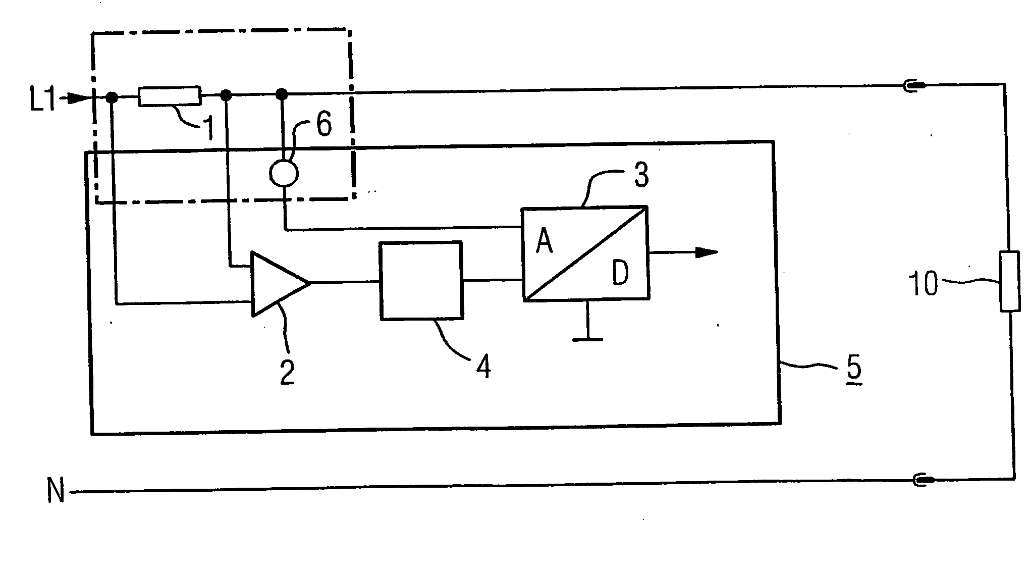
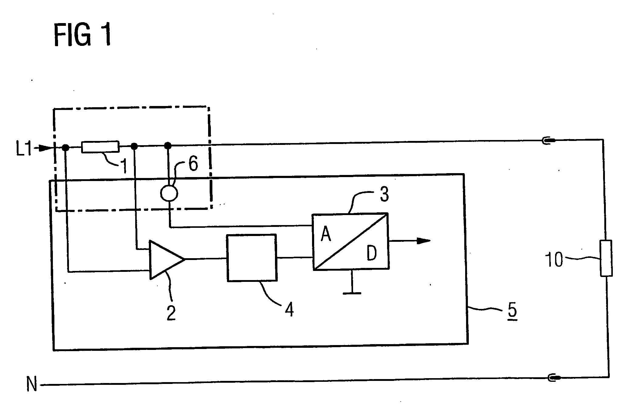
[0035]FIG. 1 shows one advantageous arrangement of the shunt resistor and measuring device. In accordance with FIG. 1 in DE 101 05 982 A1, a phase L1 that is at a high potential contains a shunt 1 which uses an amplifier 2 to provide an analog / digital converter 3 (as part of a measuring device 5) with the measurement voltage Udiff 1. The voltage difference Udiff, which is regarded as being a measure of the current through the shunt 1, is converted by the analog / digital converter (ADC) 3 into a binary measured value and is transmitted at ground potential in the form of a binary signal.

[0036] Connected upstream of the ADC...


PUM


Abstract

A method with corresponding circuit arrangement is disclosed, whereby for evaluation of a measured signal arising as an analogue value with a potential greater than zero potential in a measuring device requiring a supply current, the measured information therefrom is transmitted as a digital signal to an analytical unit lying at earth potential after an A / D conversion. The generated digital signal thus provides the clock signal for a modulation of the supply current and thus also carries out the function of the carrier for the information content of the measured signal. Curved characteristic lines for compression / decompression of the signals are used. Suitable devices for temperature compensation may be similarly provided.

Description

[0001] This application is the national phase under 35 U.S.C. § 371 of PCT International Application No. PCT / DE2003 / 002660 which has an International filing date of Aug. 7, 2003, which designated the United States of America and which claims priority on German Patent Application number DE 102 37 920.3 filed Aug. 14, 2002, the entire contents of which are hereby incorporated herein by reference.FIELD OF THE INVENTION [0002] The invention generally relates to a method for current measurement. In addition, the invention also generally relates to the associated circuit arrangement. BACKGROUND OF THE INVENTION [0003] One known method for current measurement involves measuring the voltage drop across a shunt resistor. Digital / analog converters (ADCs), which convert the analog measurement signal into a digital measured value, are frequently used in modern measuring and switching devices for the purpose of measurement. In this case, the following problems may arise: [0004] a) The measuremen...

Claims


Application Information

Patent Timeline
Patent Type & Authority Applications(United States)
IPC IPC(8): G01R15/18G01R15/14G01R19/252G01R19/32
CPCG01R15/146G01R19/252G01R19/32
Inventor MAIER, REINHARDRUPP, JURGEN
Owner SIEMENS AG
Learn More