
Method and circuit for frequency synthesis using a low drift current controlled oscillator with wide output frequency range

Active Publication Date: 2006-07-27
TEXAS INSTR INC
View PDF5 Cites 17 Cited by
  • Summary
  • Abstract
  • Description
  • Claims
  • Application Information

AI Technical Summary

Benefits of technology

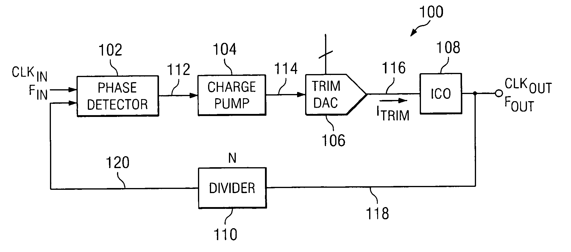
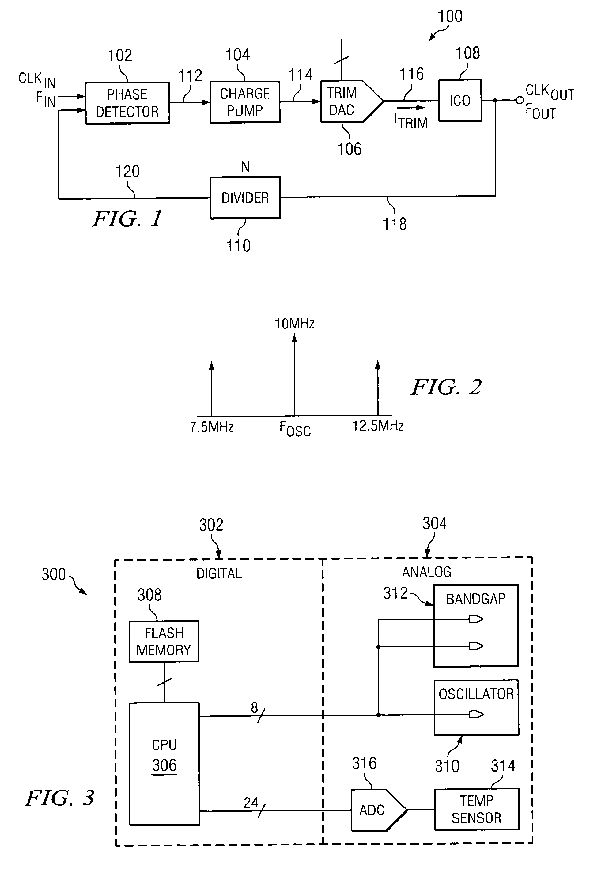
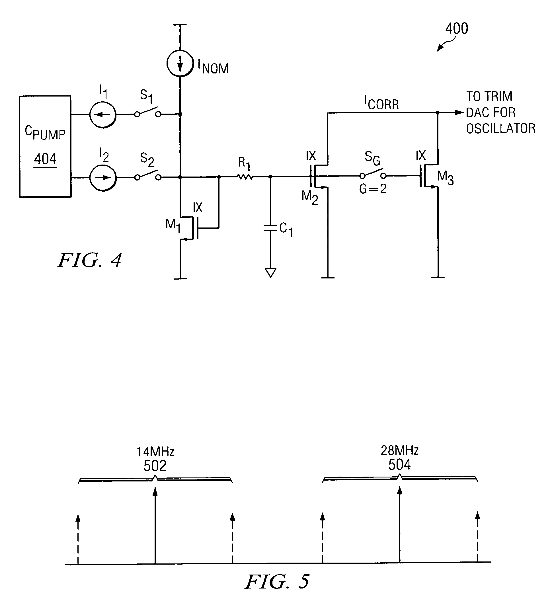
[0006] In accordance with an exemplary embodiment of the present invention, trim values for operation of the trim DAC can be suitably located within a trim register of flash memory, such as programmable flash memory within any mixed-signal device or system. Control of the flash memory can be provided through any conventional processor device. Programming of the flash memory can allow for accurate trimming values to be stored, thus enabling flash trimming by the trim DAC to very accurately control the center frequency of the current controlled oscillator.
[0007] In accordance with an exemplary embodiment, a temperature sensor can be configured within a feedback path of the processor device to facilitate lower temperature drift of the output frequency of the current controlled oscillator circuit. In addition, other parameters can be suitably monitored for adjustment of the trimmed correction signal provided to the current controlled oscillator.

Problems solved by technology

For example, while PLL circuits are able to lock certain frequencies under the majority if not all conditions of temperature and power supply variations, internal oscillators generally suffer from frequency drift over the given temperature range.
In addition to failing to produce the level of accuracy for PLL generated clock circuits, internal oscillator circuits typically have a limited frequency range.
Such techniques come at a significant cost of silicon area, as well as requiring complex analog circuitry, such as the use of loop filters and highly accurate external clock sources, to make such a circuit operate properly.

Method used


Image

  • Method and circuit for frequency synthesis using a low drift current controlled oscillator with wide output frequency range
  • Method and circuit for frequency synthesis using a low drift current controlled oscillator with wide output frequency range
  • Method and circuit for frequency synthesis using a low drift current controlled oscillator with wide output frequency range

Examples


Embodiment Construction

[0015] The present invention may be described herein in terms of various functional components and various processing steps. It should be appreciated that such functional components may be realized by any number of hardware or structural components configured to perform the specified functions. For example, the present invention may employ various integrated components, e.g., buffers, supply rail references, filtering devices, and the like, comprised of various electrical devices, e.g., resistors, transistors, capacitors, diodes and the like whose values may be suitably configured for various intended purposes. In addition, the present invention may be practiced in any integrated circuit application where accurate output frequencies are desired, and the mixed-signal devices illustrated herein are merely for exemplary purposes. Further, it should be noted that while various components may be suitably coupled or connected to other components within exemplary circuits, such connections...


PUM


Abstract

A method and circuit for frequency synthesis using a low drift current controlled oscillator configured to provide a wide output frequency and high accuracy are provided. An exemplary frequency synthesis circuit is configured for programmable control of a center frequency of the current controlled oscillator to provide a wide range of output frequencies with high accuracy. In accordance with an exemplary embodiment of the present invention, an exemplary circuit comprises a phase-locked loop (PLL) circuit comprising a phase detector, a charge pump, a current controlled oscillator and a divider circuit. For programmable control of the current controlled oscillator, the PLL circuit further comprises a trim digital-to-analog converter (DAC) configured to provide a trimmed current signal for control of the current controlled oscillator. In accordance with an exemplary embodiment of the present invention, trim values for operation of the trim DAC can be suitably located within a trim register of flash memory, such as programmable flash memory within any mixed-signal device or system.

Description

FIELD OF INVENTION [0001] The present invention relates to frequency synthesis within integrated circuits. More particularly, the present invention relates to a method and circuit for frequency synthesis using a low drift current controlled oscillator to provide a wide output frequency range. BACKGROUND OF THE INVENTION [0002] While both oscillator devices and phase-locked loop (PLL) circuits are used for frequency synthesis in generating output clock signals, internal oscillator circuits typically differ from PLL circuits in the stability or drift of the output frequency. For example, while PLL circuits are able to lock certain frequencies under the majority if not all conditions of temperature and power supply variations, internal oscillators generally suffer from frequency drift over the given temperature range. In addition to failing to produce the level of accuracy for PLL generated clock circuits, internal oscillator circuits typically have a limited frequency range. [0003] At...

Claims


Application Information

Patent Timeline
IPC IPC(8): H03L7/00
CPCH03L1/026H03L7/0891H03L7/099H03L7/10H03L7/18H03L7/1072
Inventor MOLINA, JOHNNIECHEUNG, HUGOGHOSH, RITUPARNASARIPALLI, RAMESH
Owner TEXAS INSTR INC
Learn More