A kind of uwb antenna with band-stop characteristic

An antenna and characteristic technology, applied in the field of UWB antenna, can solve the problems of increasing the volume and weight of the antenna, and achieve the effect of simple and compact structure, easy processing and easy integration

Inactive Publication Date: 2017-06-16
北京邮电大学世纪学院
View PDF5 Cites 0 Cited by
  • Summary
  • Abstract
  • Description
  • Claims
  • Application Information

AI Technical Summary

Problems solved by technology

[0004] A currently disclosed implementation is to add an additional filter at the rear end of the antenna to achieve the function of filtering out interference frequency band signals, but this is at the cost of increasing the volume and weight of the antenna
Therefore, the existing technical problem is how to improve the structural characteristics of the UWB antenna itself to achieve the band-rejection characteristics in the narrow frequency band without adding additional filters.

Method used


Image

  • A kind of uwb antenna with band-stop characteristic
  • A kind of uwb antenna with band-stop characteristic
  • A kind of uwb antenna with band-stop characteristic

Examples


Embodiment 1

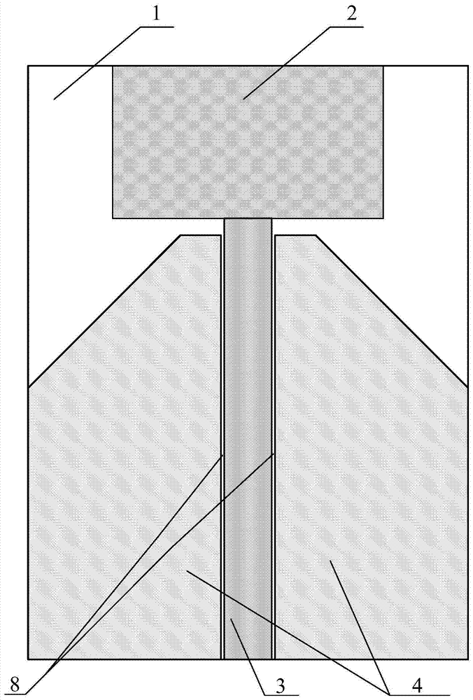
[0034] figure 1 A schematic diagram of the front structure of the band-stop UWB antenna provided by an embodiment of the present invention; figure 2 A schematic diagram of the back structure of the band-stop UWB antenna provided for an embodiment of the present invention, wherein the pattern within the range of the dotted line represents the corresponding position of each component on the front of the band-stop UWB antenna on the back, not the actual structure, nor used to limit the material of the parts . Such as figure 1 and figure 2 As shown, the band stop UWB antenna in this embodiment includes a dielectric substrate 1, and the first surface of the dielectric substrate 1 is sequentially provided with a radiation unit 2, a feeding structure 3 and two coplanar metal floors 4 from top to bottom. , the two coplanar metal floors 4 are symmetrically distributed on both sides of the feed structure 3, and the feed structure 3 is connected to the radiation unit 2; on the secon...

Embodiment 2

[0037] This embodiment is similar to the structure of the band-stop UWB antenna provided in Embodiment 1, the difference is that, as figure 1 and figure 2 As shown, the first area and the second area are the corresponding areas on the second surface of the coplanar waveguide 8 of the first surface, wherein the coplanar waveguide 8 is the feed structure 3 and the coplanar waveguide 8. Two slit-shaped structures formed by the metal floor 4, the feed structure 3 serves as the conduction band of the coplanar waveguide, and the coplanar metal floor 4 serves as the ground of the coplanar waveguide.

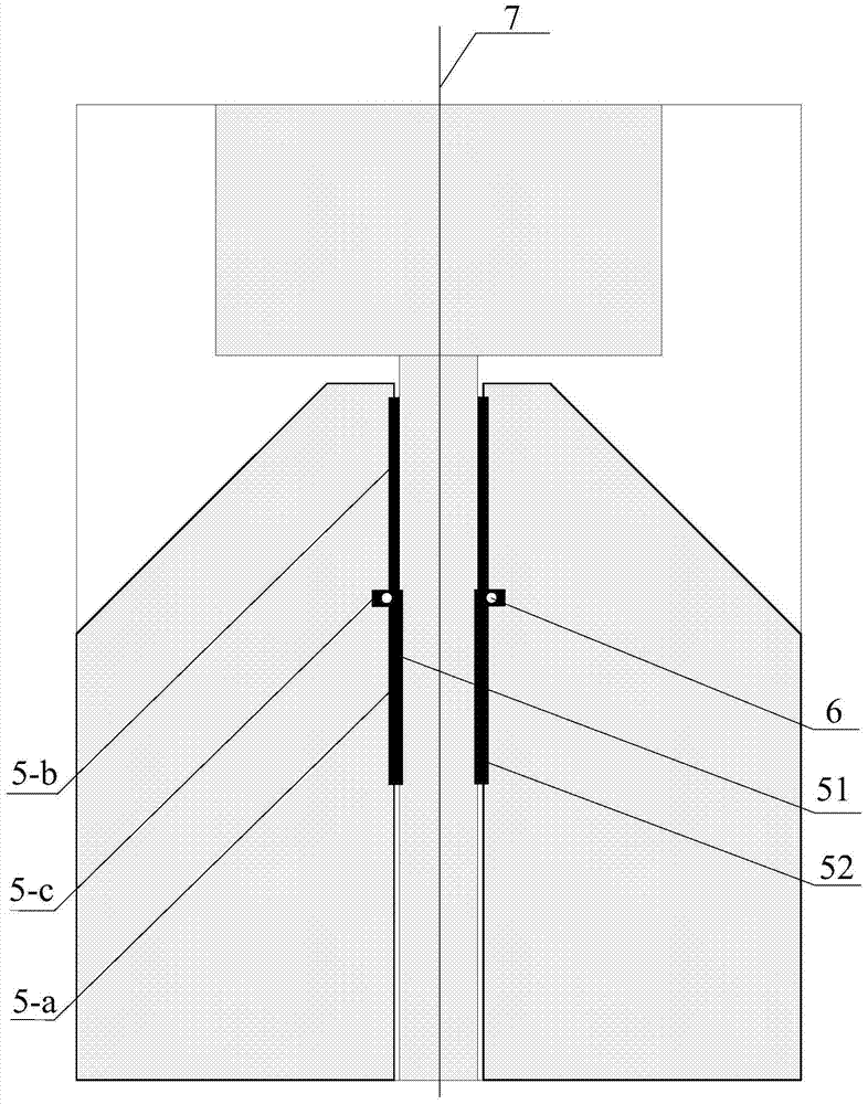
[0038] Such as figure 2 As shown, the first microstrip resonator 51 and the second microstrip resonator 52 have the same shape, and they are distributed symmetrically on the antenna with the central axis 7 as the reference. The first microstrip resonator 51 on the left is taken as an example below to illustrate The structure of the resonator:

[0039] The first resonator 51 include...


PUM


Abstract

The invention provides a UWB antenna with band-rejection characteristics, comprising a dielectric substrate, a radiation unit, a feed structure and a coplanar metal floor are arranged on the first surface of the dielectric substrate, the radiation unit and the feed structure connected; on the second surface of the dielectric substrate, a first microstrip resonator is arranged in the first region; on the second surface of the dielectric substrate, a second microstrip resonator is arranged in the second region; the first The microstrip resonator and the second microstrip resonator are respectively connected to the coplanar metal floor through metal connecting parts. The present invention can realize notch wave characteristics within the preset frequency range, and can conveniently control the center frequency of the stop band by controlling the resonance length of the microstrip resonator, and has the advantages of convenient design, easy processing, low cost and simple structure Advantages of compactness, miniaturization and ease of integration with active circuits.

Description

technical field [0001] The invention relates to an ultra-wideband antenna in the field of wireless communication, in particular to a UWB antenna with band-stop characteristics. Background technique [0002] In recent years, with the advancement of modern microelectronics technology and the development of high-speed devices, ultra-wideband (UWB) wireless technology has begun to be used by civilians. UWB has super-strong wireless device connection capabilities, and has the advantages of high performance, low power consumption and low cost, and has become one of the most competitive technologies. In recent years, there have been many researches on antennas used in short-distance wireless communication, and many new forms of UWB antennas have emerged. [0003] The current research mainly focuses on UWB antennas capable of omnidirectional radiation, and its main types are microstrip antennas, microstrip slot antennas and flat-panel monopole antennas. The frequency band of UWB s...

Claims


Application Information

Patent Timeline
Patent Type & Authority Patents(China)
IPC IPC(8): H01Q1/38H01Q13/08
Inventor 杨慧春毕战红张震
Owner 北京邮电大学世纪学院
Why Eureka
Try Eureka