UWB antenna with band-stop characteristic
An antenna and characteristic technology, applied in the field of UWB antenna, can solve the problems of increasing the volume and weight of the antenna, and achieve the effect of simple and compact structure, miniaturization and integration, and convenient design
- Summary
- Abstract
- Description
- Claims
- Application Information
AI Technical Summary
Problems solved by technology
Method used
Image
Examples
Embodiment 1
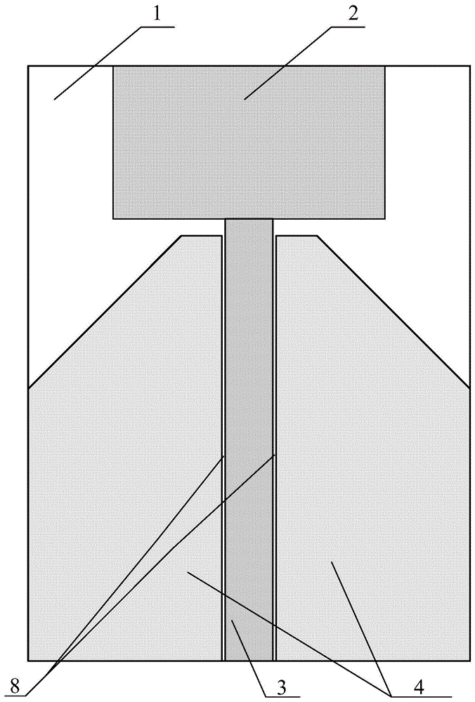
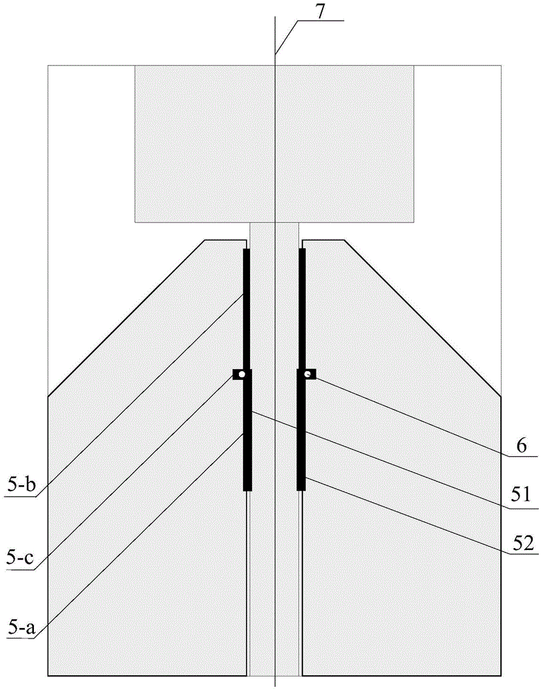
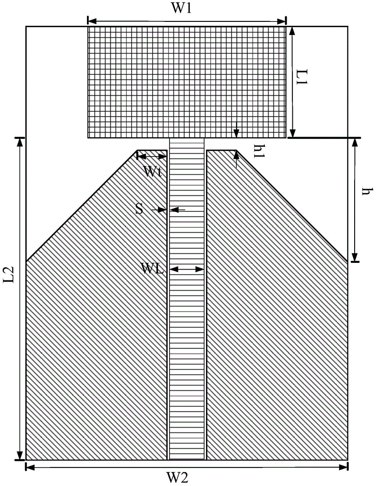
[0034] figure 1 A schematic diagram of the front structure of the band-stop UWB antenna provided by an embodiment of the present invention; figure 2 A schematic diagram of the back structure of the band-stop UWB antenna provided for an embodiment of the present invention, wherein the pattern within the range of the dotted line represents the corresponding position of each component on the front of the band-stop UWB antenna on the back, not the actual structure, nor used to limit the material of the parts . like figure 1 and figure 2 As shown, the band stop UWB antenna in this embodiment includes a dielectric substrate 1, and the first surface of the dielectric substrate 1 is sequentially provided with a radiation unit 2, a feeding structure 3 and two coplanar metal floors 4 from top to bottom. , the two coplanar metal floors 4 are symmetrically distributed on both sides of the feed structure 3, and the feed structure 3 is connected to the radiation unit 2; on the second s...
Embodiment 2
[0037] This embodiment is similar to the structure of the band-stop UWB antenna provided in Embodiment 1, the difference is that, as figure 1 and figure 2 As shown, the first area and the second area are the corresponding areas on the second surface of the coplanar waveguide 8 of the first surface, wherein the coplanar waveguide 8 is the feed structure 3 and the coplanar waveguide 8. Two slit-shaped structures formed by the metal floor 4, the feed structure 3 serves as the conduction band of the coplanar waveguide, and the coplanar metal floor 4 serves as the ground of the coplanar waveguide.
[0038] like figure 2 As shown, the first microstrip resonator 51 and the second microstrip resonator 52 have the same shape, and they are distributed symmetrically on the antenna with the central axis 7 as the reference. The first microstrip resonator 51 on the left is taken as an example below to illustrate The structure of the resonator:
[0039] The first resonator 51 includes: ...
PUM
| Property | Measurement | Unit |
|---|---|---|
| Length | aaaaa | aaaaa |
| Length | aaaaa | aaaaa |
| Diameter | aaaaa | aaaaa |
Abstract
Description
Claims
Application Information
 - R&D
- Intellectual Property
- Life Sciences
- Materials
- Tech Scout
- Unparalleled Data Quality
- Higher Quality Content
- 60% Fewer Hallucinations
Browse by: Latest US Patents, China's latest patents, Technical Efficacy Thesaurus, Application Domain, Technology Topic, Popular Technical Reports.
© 2025 PatSnap. All rights reserved.Legal|Privacy policy|Modern Slavery Act Transparency Statement|Sitemap|About US| Contact US: help@patsnap.com


