Visual acuity chart displaying apparatus and optometry apparatus

a visual acuity chart and display apparatus technology, applied in the field of visual acuity chart display apparatus, can solve the problems of increased thickness of the apparatus and manufacturing cost of the apparatus, inconvenient operation, uneven brightness and contrast of the indicated index, etc., and achieve the effect of reducing the siz

Inactive Publication Date: 2006-07-27
KK TOPCON
View PDF7 Cites 12 Cited by
  • Summary
  • Abstract
  • Description
  • Claims
  • Application Information

AI Technical Summary

Benefits of technology

[0014] The present invention has been made in view of the above-mentioned circumstances. An object of the present invention is to provide a visual acuity chart displaying apparatus and an optometry apparatus, each of which can be thinned and reduced in size.

Problems solved by technology

Therefore, there is a problem in that an inconvenience occurs, for example, in the case where a set space for the apparatus is limited.
When the index is illuminated with light radially emitted from the lamp, there is the case where the indicated index has some unevenness in brightness and contrast because the flat index plate and the flat chart are not uniformly illuminated.
However, there occurs a problem in that the thickness of the apparatus and a manufacturing cost thereof increase as the number of parts increases.
Therefore, when a limitation on the size of the apparatus is taken into account, the types of usable indexes and the number of usable indexes are also limited accordingly.
In particular, although a Landolt ring is one of most normally used indexes, a Landolt ring for a lower visual acuity value (for example, 0.1) requires a large area for display on the index plate or the like, so the number of index plates or the number of sheets on which other indexes are formed is limited.
Thus, it is difficult to perform various examinations by a single visual acuity chart displaying apparatus.
Because the indexes which are printed on or bonded to the index plate or the sheet are used, it is impossible to use variable indexes such as indexes for dynamic vision examination.
In the optometry apparatus described in JP 06-142052 A, the light source for index illumination is provided in the rear of the index, which makes it difficult to reduce the size (thickness) of the apparatus.
Therefore, as in the cases of the visual acuity chart displaying apparatuses described in JP 04-300518 A and JP 06-245904 A, an inconvenience occurs, for example, in the case where the set space for the apparatus is limited.
However, because of the limitation on the number of dots of the liquid crystal display plate, there is a problem in that a small index (for example, a Landolt ring for a higher visual acuity value of 2.0) cannot be minutely expressed unlike the structure using the index plate or the like.

Method used


Image

  • Visual acuity chart displaying apparatus and optometry apparatus
  • Visual acuity chart displaying apparatus and optometry apparatus
  • Visual acuity chart displaying apparatus and optometry apparatus

Examples


first embodiment

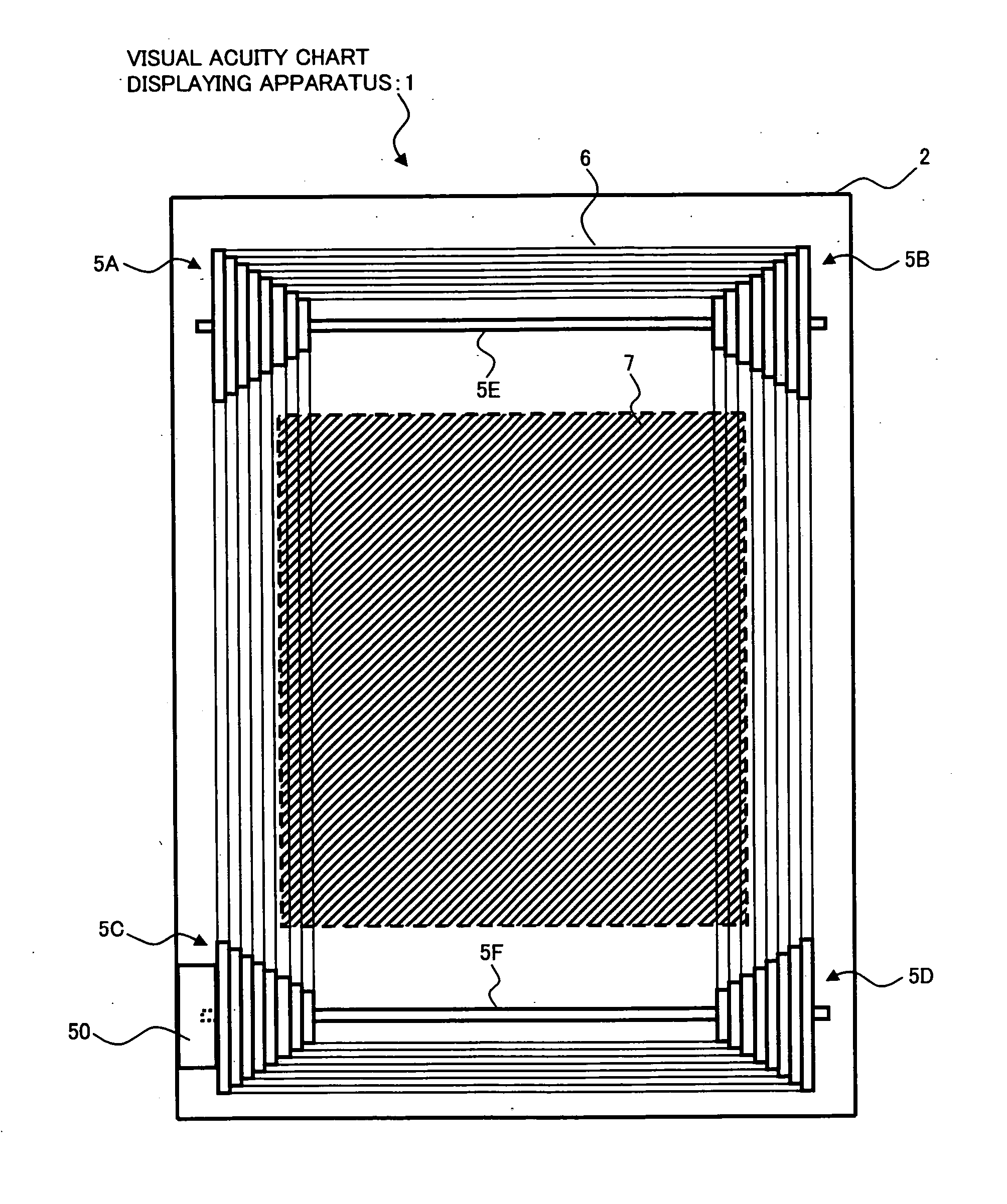
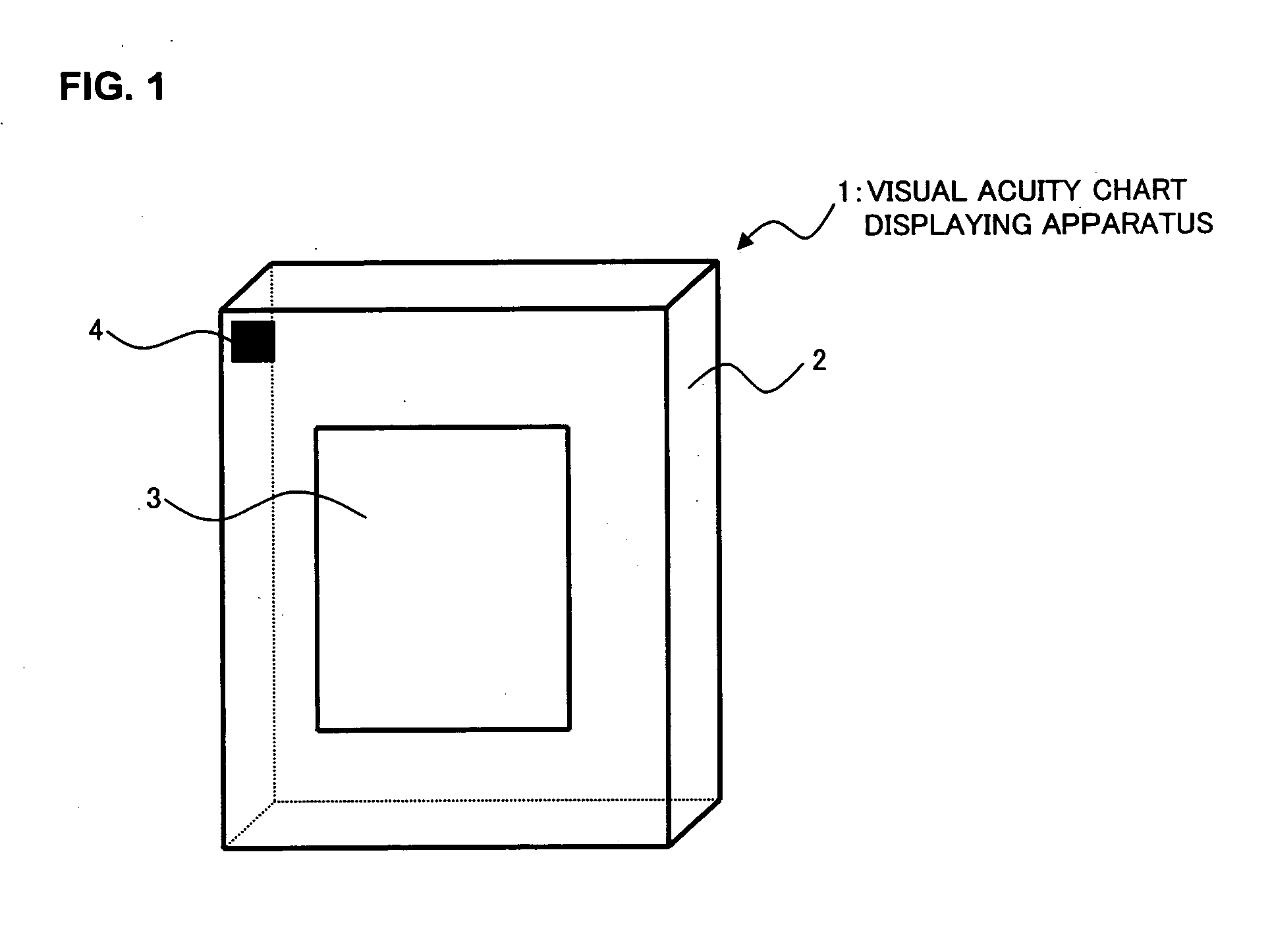
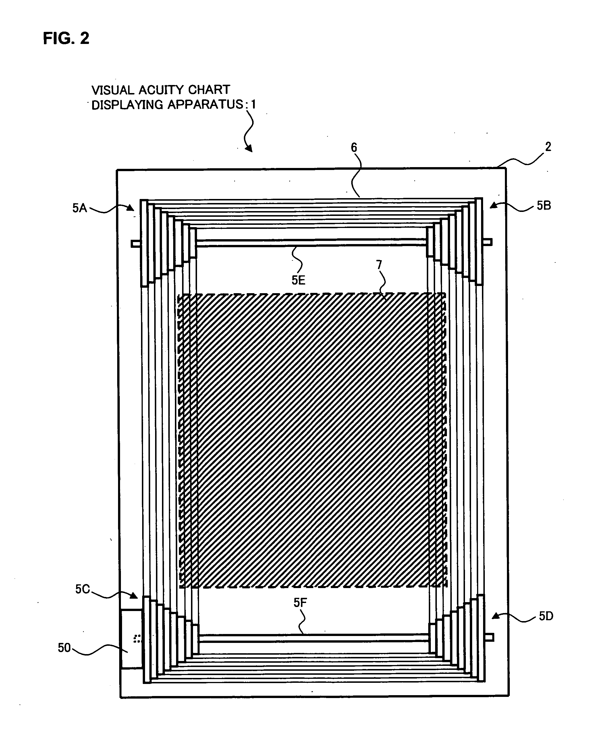
[0045]FIGS. 1, 2, and 3 are schematic views showing the entire structure of the visual acuity chart displaying apparatus according to the first embodiment of the present invention. FIG. 1 is a schematic perspective view showing an external structure of the visual acuity chart displaying apparatus when the apparatus is viewed from the front. FIG. 2 is a schematic perspective view showing an internal structure of the visual acuity chart displaying apparatus when the apparatus is viewed from the front. FIG. 3 is a schematic sectional view showing the internal structure of the visual acuity chart displaying apparatus in section when the apparatus is viewed from the side.

[0046] A visual acuity chart displaying apparatus 1 according to this embodiment includes an apparatus box 2, an index display window 3 which is opened in the center of a front surface 2A of the apparatus box 2, and a receiver 4 for receiving an operating signal (such as an infrared signal) from a remote controller (des...

second embodiment

[0077] Next, a visual acuity chart displaying apparatus according to another embodiment of the present invention will be described. The visual acuity chart displaying apparatus according to this embodiment has, for example, the same structure as that in the first embodiment except the control system. In the following description, the same reference numerals are provided for the same constituent parts as those in the first embodiment. The contents described in the first embodiment can be arbitrary applied to this embodiment.

[0078]FIG. 9 shows an example of a control system of a visual acuity chart displaying apparatus 1′ according to this embodiment. The CPU 70 includes a mode switching control unit 71 (control means) for switching between operational modes for projecting the index on the eye to be examined (not shown) (index indicating modes) and a display control unit 72 for controlling the liquid crystal display device 7.

[0079] The index indicating modes used for the visual acui...

modified examples

[0092] A modified example of the visual acuity chart displaying apparatus 1′ according to this embodiment will be described. When the plurality of indexes such as the visual acuity test charts and the Landolt test charts as shown in FIG. 7 are set in the position in which the index display window 3 is located in the first index indicating mode, the control is made such that only a region of the liquid crystal display device 7 is lighted. Therefore, of the plurality of indexes, one index or two or more indexes can be selectively illuminated to project the indexes on the eye to be examined. A lighting region of the liquid crystal display device 7 is changed by the display control unit 72 in response to, for example, an index selection input from the remote controller 8. For example, when the Landolt test chart having twelve Landolt rings provided thereon as shown in FIG. 7 is used, the Landolt ring indicated to the eye to be examined can be changed using cursor keys (not shown) of the...


PUM


Abstract

A visual acuity chart displaying apparatus, which is thin, has many indexes, including minutely small index. It includes a first index indicating mode for illuminating the film member having indexes from the rear lighting the liquid crystal display device, and a second mode for retreating the film member from the position located in front of the liquid crystal device and displaying the index pattern on the liquid crystal display device to project the index or index pattern on the eye to be examined, and a mode switching control unit of the CPU to switch between the first and second mode.

Description

BACKGROUND OF THE INVENTION [0001] 1. Field of the Invention [0002] The present invention relates to a visual acuity chart displaying apparatus for indicating an optometry index(optotype) (hereinafter referred to as merely “index(es)”) to an eye to be examined and an optometry apparatus for measuring visual acuity of the eye to be examined based on how an examinee to view the index. [0003] 2. Description of the Related Art [0004] In optometry measurement using indexes, the indexes are indicated to an eye to be examined by a visual acuity chart displaying apparatus or an optometry apparatus as described in JP 04-300518 A (claims, specification paragraph [0011], and FIG. 1), JP 06-245904 A (claims and specification paragraphs [0008] to [0011]), JP 06-142052 A (specification paragraph [0012] and FIG. 1), JP 06-254050 A (claims, specification paragraph [0012], and FIG. 1), or JP 11-235313 A (specification paragraph [0009] and FIG. 1). When an examinee makes a response to a question aski...

Claims


Application Information

Patent Timeline
Patent Type & Authority Applications(United States)
IPC IPC(8): A61B3/02
CPCA61B3/032E04G9/06E04G17/04E04G2009/025
Inventor IKEZAWA, YUKIO
Owner KK TOPCON
Why Eureka
Try Eureka