Magnetic recording/reproduction apparatus

a recording and reproduction apparatus technology, applied in the field of magnetic recording/reproduction apparatus, can solve the problems of not being able to realize the intermittent video recording provided with relatively small intervals, failing to record a picture, and not being able to achieve the shortening of the video recording interval,

Inactive Publication Date: 2006-07-27
GK BRIDGE 1
View PDF8 Cites 11 Cited by
  • Summary
  • Abstract
  • Description
  • Claims
  • Application Information

AI Technical Summary

Benefits of technology

[0023] In the inventions according to 1) and 2), it is preferable to reproduce a time code in the previously recoded auxiliary information and positioned immediately prior to a recording-start position on the recording medium where the recording device starts the recording next, generate a regeneration value obtained by adding a frame to the reproduced time code when the next recording starts, replace the time code in the auxiliary information outputted from the auxiliary information memorizing section with a serial value starting with the regeneration value to thereby record it as the auxiliary information. Further, it is preferable to correct the regeneration value by an amount of delay corresponding to a storage volume memorized in the auxiliary information memorizing section to thereby reflect the regeneration value on a time code generating section so that a time difference between the time code on the tape and the time code generating section can be eliminated.

Problems solved by technology

Therefore, when the video signal recording apparatus is used in the news coverage and the like, there is a risk that the recording may be performed failing to record a picture or audio at a moment when the photographer wishes to record, in which some scenes to be captured are missing.
However, because of the presence of the time lag, the intermittent video photographing provided with relatively large photographing intervals of a few seconds to a few minutes can be performed, while failing to realize the intermittent video photographing provided with relatively small intervals shorter than the time lag, for example, one second or less.
Because of the mentioned problems, it is not easy to assure an accuracy in setting the photographing intervals of the intermittent video photographing (in particular, accuracy in setting minimum photographing intervals).
Because of that, the auxiliary information is unavoidably temporally delayed relative to the video audio signal on the recording medium.
Therefore, a relationship between the video audio signal recorded on the recording medium and the auxiliary information is lost, which makes it difficult to effectively utilize the auxiliary information.
The CUE audio signal, as in the case of the other auxiliary information, undergoes a deteriorated accuracy in the search operation at the time of fast forward / fast rewind reproduction when there is any temporal delay relative to the video audio signal.

Method used


Image

  • Magnetic recording/reproduction apparatus
  • Magnetic recording/reproduction apparatus
  • Magnetic recording/reproduction apparatus

Examples


first embodiment

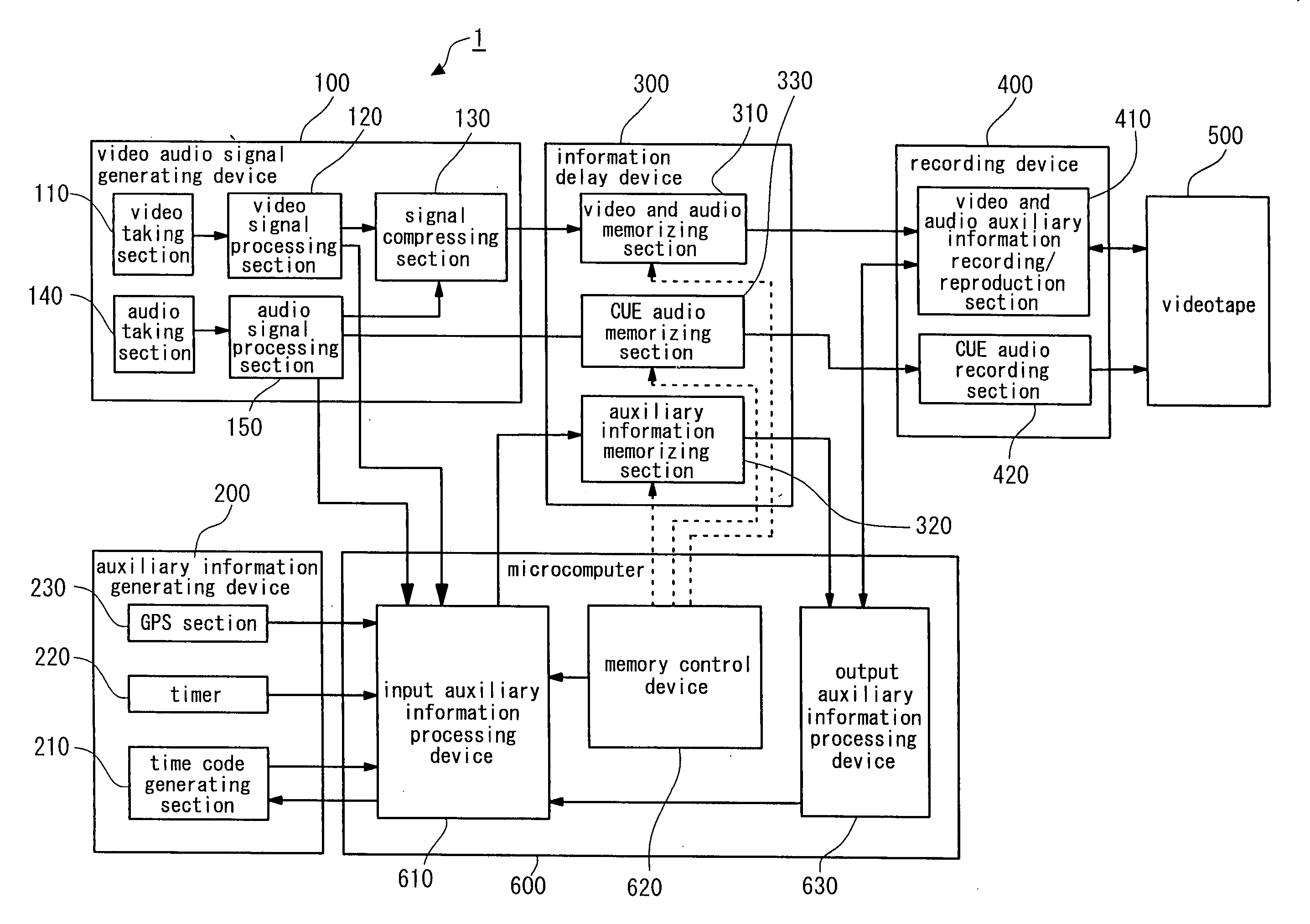
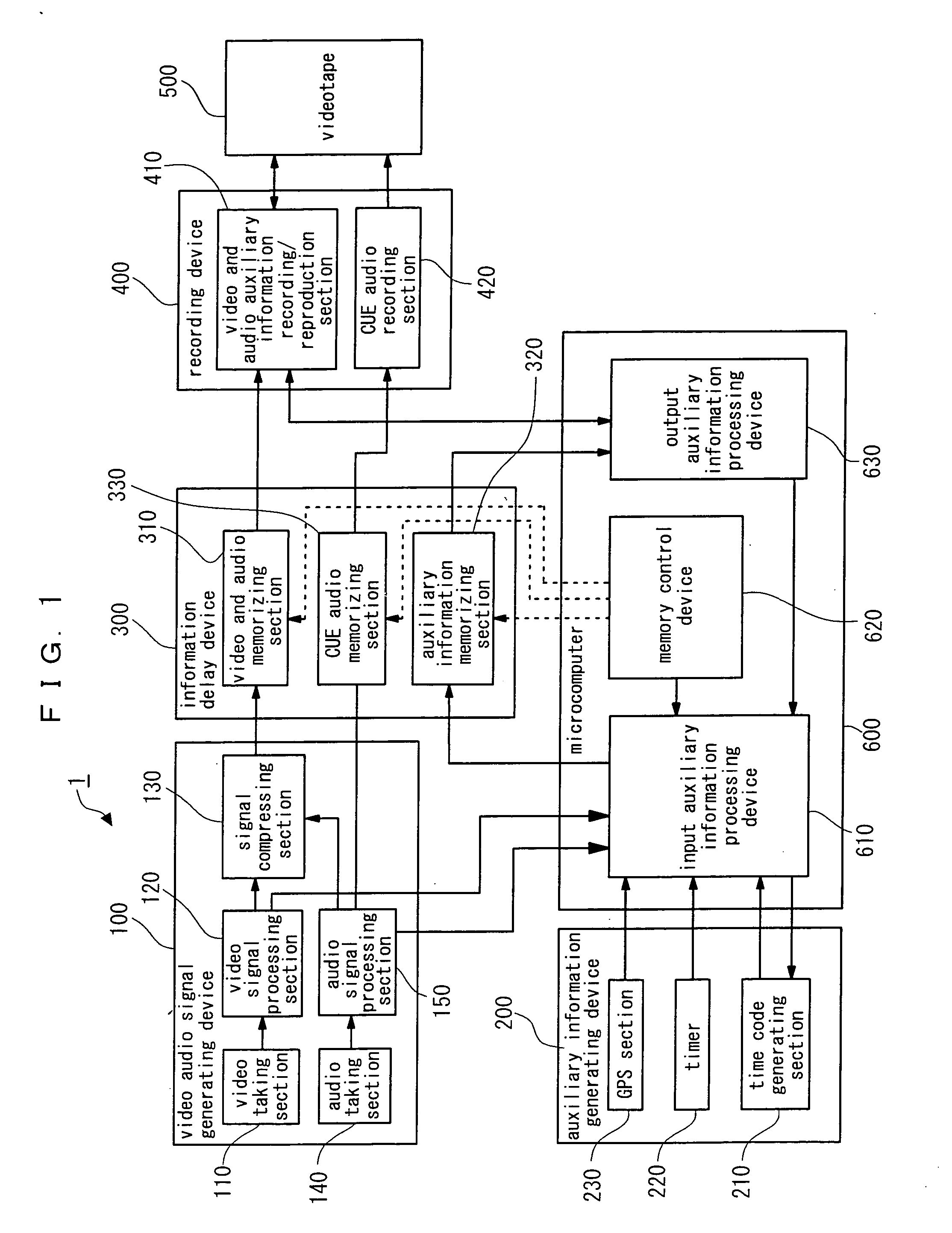
[0031]FIG. 1 is a block diagram illustrating a configuration of a magnetic recording / reproduction apparatus 1 according to a first embodiment of the present invention. The magnetic recording / reproduction apparatus 1 comprises, as shown in FIG. 1, a video audio signal generating device 100, an auxiliary information generating device 200, an information delay device 300, a recording device 400, a videotape 500, and a micro computer 600.

[0032] The video audio signal generating device 100 comprises a video taking section 110 comprised of a lens, CCD and the like, a video signal processing section 120 for applying a digital processing or the like to a video signal obtained by the video taking, a signal compressing section 130 for applying a compression encoding to the digital video signal, an audio taking section 140 comprised of a microphone, an audio signal generator and the like, and an audio signal processing section 150 for applying a digital processing or the like to an audio sign...


PUM

PropertyMeasurementUnit
time lagaaaaaaaaaa
time lengthaaaaaaaaaa
timeaaaaaaaaaa

Abstract

An inputted video audio signal is temporarily memorized in a video and audio memorizing section 310. Auxiliary information appended to the video audio signal is temporarily memorized in an auxiliary information memorizing section 320. A memory control device 620 controls write and read operations of the video audio signal with respect to the video and audio memorizing section 310 and write and read operations of the auxiliary information with respect to the auxiliary information memorizing section 320. The video audio signal read from the video and audio memorizing section 310 and the auxiliary information read from the auxiliary information memorizing section 320 are sequentially recorded on a recording medium 500 by a recording device 400. The memory control device 620 stores the video audio signals equivalent to a time length equal to or exceeding an amount of time required from a time point when a recording-start request with respect to the recording medium 500 is made until the recording actually starts with respect to the recording medium 500 in the video and audio memorizing section 310 to thereby delay the video audio signals by an amount of time during which the video audio signals are stored and records the delayed video audio signals on the recording medium. The memory control device 620 further stores the auxiliary information appended to the video audio signals in the auxiliary information memorizing section 320 for a time period substantially equal to the delay of the video audio signals to thereby delay the auxiliary information by an amount of time during which the auxiliary information is stored and records the delayed auxiliary information on the recording medium 500.
The video audio signal and its relevant auxiliary information (time code, metadata, CUE audio signal, and the like) can be thereby recorded on the recording medium 500 with no time delay relative to each other.

Description

FIELD OF THE INVENTION [0001] The present invention relates to a magnetic recording / reproduction apparatus, more particularly to a magnetic recording / reproduction apparatus used for news coverage, a crime prevention system, animation photographing, and the like, and capable of an intermittent video photographing. BACKGROUND OF THE PRESENT INVENTION [0002] A camera-incorporated videotape recorder, which is an apparatus for recording a video signal, is used for news coverage and the like because of its portability. In using the video signal recording apparatus of such a type, a recording time is restricted in response to a capacity of a videotape as a recording medium. Therefore, a photographer generally leaves the recording apparatus in a recording standby state until a scene which he / she wishes to record arrives, and switchovers the apparatus to a recording state when the scene which he / she wishes to record arrives to thereby record the desired scene. In the video signal recording a...

Claims


Application Information

Patent Timeline
Patent Type & Authority Applications(United States)
IPC IPC(8): H04N5/91G06F21/10G11B20/10G11B20/12G11B27/00G11B27/02G11B27/032G11B27/28H04N5/77H04N5/92H04N19/89
CPCG11B20/10527H04N5/772H04N5/9201G11B20/10H04N5/91
Inventor NODA, AKIYUKITAKEMOTO, SHINJIYAMASHITA, HIROYUKIFUJIMOTO, TSUNEKI
Owner GK BRIDGE 1
Why Eureka
Try Eureka