Composite abrasive compact

a technology of abrasives and compacts, applied in the direction of grinding machines, other manufacturing equipment/tools, gear teeth, etc., can solve the problems of abrasive compacts that are predisposed to premature failure by spalling, abrasive compacts that are stressed, etc., and achieve the effect of minimising mechanical/elastic stresses

Inactive Publication Date: 2006-07-27
TANK KLAUS +1
View PDF11 Cites 56 Cited by
  • Summary
  • Abstract
  • Description
  • Claims
  • Application Information

AI Technical Summary

Benefits of technology

[0021] The surface of the substrate in contact with the abrasive compact layer may be planar or non-planar, including profiled surfaces. A non-planar surface minimises the mechanical / elastic stresses created as a result of the high pressure / high temperature (HPHT) sintering procedure followed to produce the composite abrasive compact.

Problems solved by technology

Abrasive compacts tend to be brittle and in use such compacts are frequently bonded to a cemented carbide substrate to afford support.
In service, such a stressed abrasive compact is predisposed to premature failure by spalling, delamination and other mechanisms.
That is to say, the abrasive compact fails prematurely due to separation and loss of all or part of the abrasive layer from the cutting surface of the abrasive compact, and the higher the residual stresses, the greater is the probability of premature failure.

Method used


Image

  • Composite abrasive compact
  • Composite abrasive compact

Examples


Embodiment Construction

[0026] The ultra-hard abrasive particles may be diamond or cubic boron nitride, but are preferably diamond particles.

[0027] The substrate is preferably a cemented carbide substrate such as cemented tungsten carbide, cemented tantalum carbide, cemented titanium carbide, cemented molybdenum carbide or a mixture thereof. The cemented carbide substrate may contain particles of a grain inhibiting agent such titanium carbide, tantalum carbide, vanadium carbide or a mixture thereof. The binder metal for such cemented carbide may be any known in the art such as nickel, cobalt, iron or an alloy containing one or more of these metals. Typically the binder will be present in an amount of 6 to 20% by mass. Some of the binder metal may infiltrate the abrasive compact during the HPHT treatment. A shim or layer of binder may be used for this purpose.

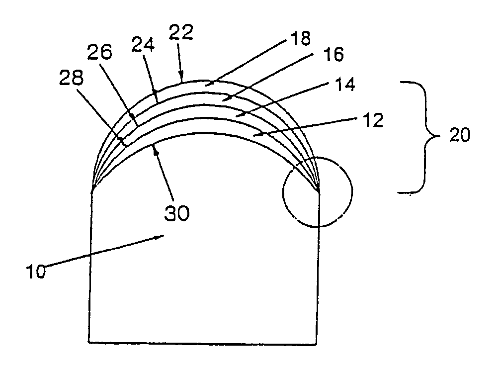
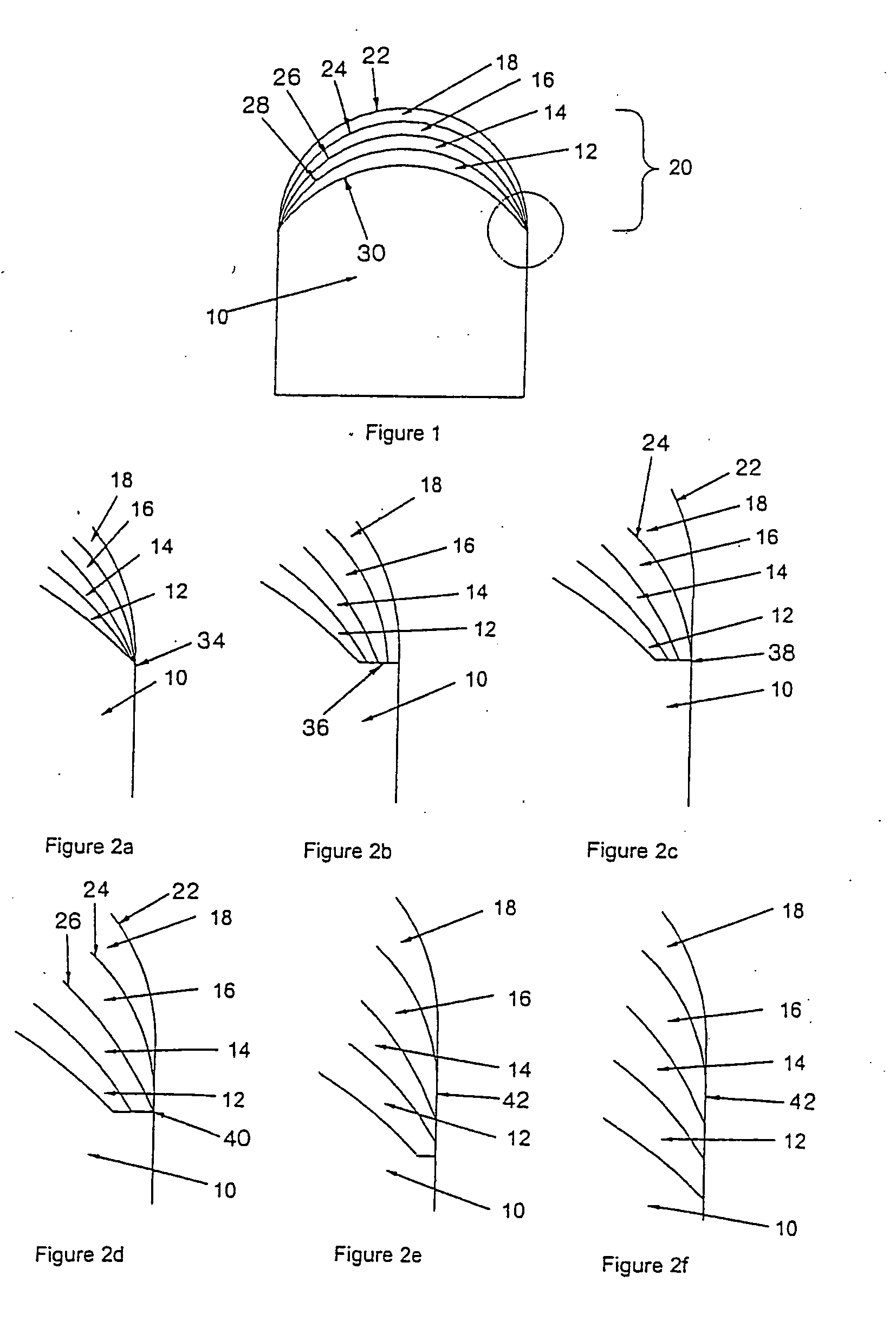
[0028] To improve the service life of a composite abrasive compact, it is necessary to reduce the residual stresses induced in the compact as a resu...


PUM

PropertyMeasurementUnit
volume percentaaaaaaaaaa

Abstract

A composite abrasive compact comprises an abrasive compact layer, generally a diamond abrasive compact layer, bonded to a substrate. The abrasive compact layer is characterised by: (i) an inner region, in contact with a surface of the substrate, (ii) a first intermediate region in contact with the inner region, (iii) a second intermediate region in contact with the first intermediate region, (iv) an outer region in contact with the second intermediate region and containing ultra-hard abrasive particles having at least three different average particle sizes, and (v) the composition in the inner region, and first and second intermediate regions varying in composition such that there is a graduated change in thermal expansion of the abrasive compact layer between the substrate and the outer region.

Description

BACKGROUND OF THE INVENTION [0001] The present invention relates to a composite abrasive compact. [0002] Abrasive compacts are used extensively in cutting, milling, grinding, drilling, boring and other abrasive operations. Abrasive compacts comprise a mass of abrasive particles, often diamond or cubic boron nitride particles, bonded into a coherent polycrystalline conglomerate. The content of abrasive particles in the compact is high, and there is generally an extensive amount of direct bonding of abrasive particles one to another, particularly in the case of diamond compacts. Abrasive compacts containing diamond or cubic boron nitride are generally made under conditions of elevated pressure and elevated temperature (HPHT conditions) at which the abrasive particles are thermodynamically stable. [0003] Diamond abrasive compacts are also referred to as polycrystalline diamond, PCD or PDC. Cubic boron nitride compacts are also known as polycrystalline cBN or PcBN. [0004] Abrasive compa...

Claims


Application Information

Patent Timeline
Patent Type & Authority Applications(United States)
IPC IPC(8): B23F21/03B24D3/00E21B10/46B24D7/18E21B10/56E21B10/567
CPCB22F7/06B22F2005/001B22F2005/002B22F2999/00C22C26/00C22C2204/00E21B10/5673B22F2207/03E21B10/56
Inventor TANK, KLAUSJONKER, CORNELIS ROELOF
Owner TANK KLAUS
Why Eureka
Try Eureka