
Method of discovering multi-mode mobile terminals

a mobile terminal and multi-mode technology, applied in substation equipment, electrical equipment, network traffic/resource management, etc., can solve the problems of sparse information available to the system about exact locations and areas, and achieve the effect of facilitating inter-network working

Active Publication Date: 2006-07-27
DOLBY LAB LICENSING CORP
View PDF2 Cites 169 Cited by
  • Summary
  • Abstract
  • Description
  • Claims
  • Application Information

AI Technical Summary

Benefits of technology

[0016] The present invention is based on the insight by the applicant that multi-mode mobile terminals can readily inform their home network of those foreign networks to which they can attach. The data gathered by the home network from multi-mode terminals can greatly facilitate interworking of networks and has a wide range of uses for both static and moving multi-mode mobile terminals.
[0023] Step (a) may be performed by tuning to a control channel of the foreign network. Gathering of the various foreign network indicators for each multi-mode mobile terminal has a wide number of uses to facilitate interworking, including: assisting vertical handover and load balancing between different networks; service delivery i.e. receiving a request for a service (e.g. a video clip) through the home network and delivering it through the foreign network; and network coverage: users that are able to listen to networks other than their home network effectively increase the coverage of the home network. For example, the multi-mode terminal may measure the RSSI for its home network and the RSSI for the or each foreign network to which it has access; if the RSSI for the or each foreign network indicates a better quality of service can be attained using the foreign network, the multi-mode terminal may inform the home network so that data can be delivered via the foreign network. It will be appreciated that this will have practical application near the limits of coverage of the home network: if the foreign network provides coverage in that area, the coverage of the home network can effectively be extended by delivering data using the foreign network. Particular advantages in signalling efficiency can be realised when the database is used to assist vertical group handovers and load balancing for both moving and static users. Step (c) may comprise the step of transmitting all of the data received from the foreign network to the home network; transmission of all of the data may take place only when the MMT issues a service request.
[0036] In one embodiment said home radio communication network has access to a database comprising a mapping between said foreign network indicator and a network layer address, the method further comprising the step of querying said database using said foreign network indicator to discover said network layer address, which network layer address provides a way for said home radio communication network to communicate substantially directly or indirectly with said foreign radio communication network. The network layer address may be an interface on a network node of said foreign radio communication network, or may be an interface on a network node external to the foreign radio communication network. If external, the network layer address may be of an interface on a SIP server for example. Accordingly, the network layer address may be an IP address or a URI for example. Using the foreign network indicator to look up the network layer address provides a convenient way for the home radio communication network to establish communication with the foreign radio communication network.
[0037] Advantageously, the method further comprises the step of handing over service from said home radio communication network to said foreign radio communication network for multi-mode mobile terminals of said at least one group. Handover may be desired for a number of reasons including more efficient use of network resources, load balancing, reduction of costs, reduction of signalling overhead for moving MMTs, etc.
[0038] Preferably, said handover step comprises the step of handing over a downlink only, whereby each multi-mode terminal of said at least one group uses an uplink of said home radio communication network and a downlink of said foreign radio communication network. In this way load balancing between networks may be improved. It will be appreciated that in certain circumstances it may be advantageous to hand over the uplink only so that each MMT uses the downlink provided by the home network and the uplink provided by the foreign network.
[0040] Preferably, said instructing step comprises the step of transmitting data with an instruction to enable each multi-mode mobile terminal to tune to the correct frequency and channel of the foreign radio communication network. This facilitates the handover process particularly if the MMT is switching to a uni-directional broadcast network where no uplink is available. In one embodiment the foreign radio communication network is a digital broadcast network (e.g. DVB) and the data comprises one or more Packet Identifier (PID) to enable the MMT to filter the correct Transmission Stream (TS) Logical Channel from the TS Multiplex.

Problems solved by technology

Enabling the system to recognise whether terminals are moving in a group is a challenge for a number of reasons, as information available to the system about the exact locations of terminals—aside from their current cell or location area—is often sparse.
Whilst this is operable in a cellular communications environment (albeit between different generations) it is not clear how such a technique might work in a heterogeneous environment where there is limited communication and co-operation between different network types and operators at best.

Method used


Image

  • Method of discovering multi-mode mobile terminals
  • Method of discovering multi-mode mobile terminals
  • Method of discovering multi-mode mobile terminals

Examples


Embodiment Construction

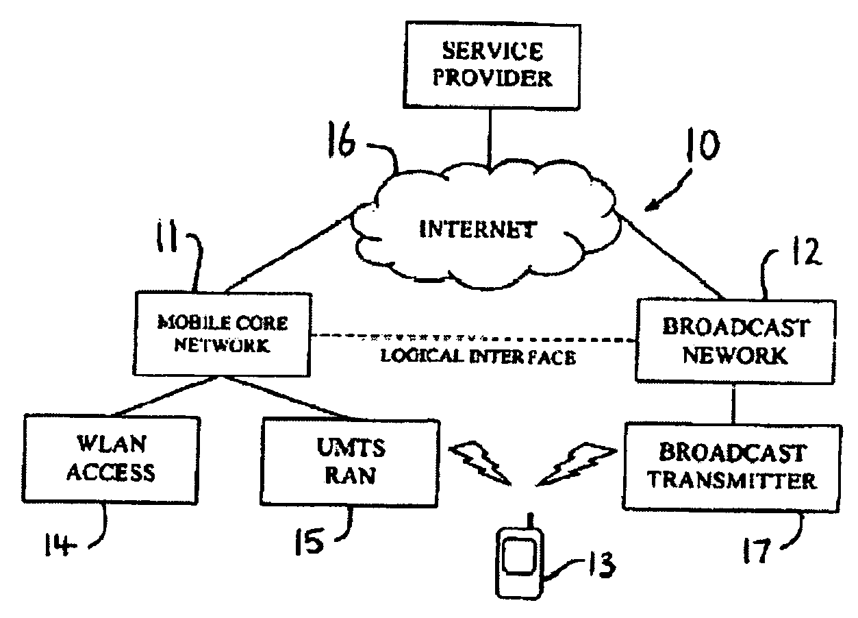
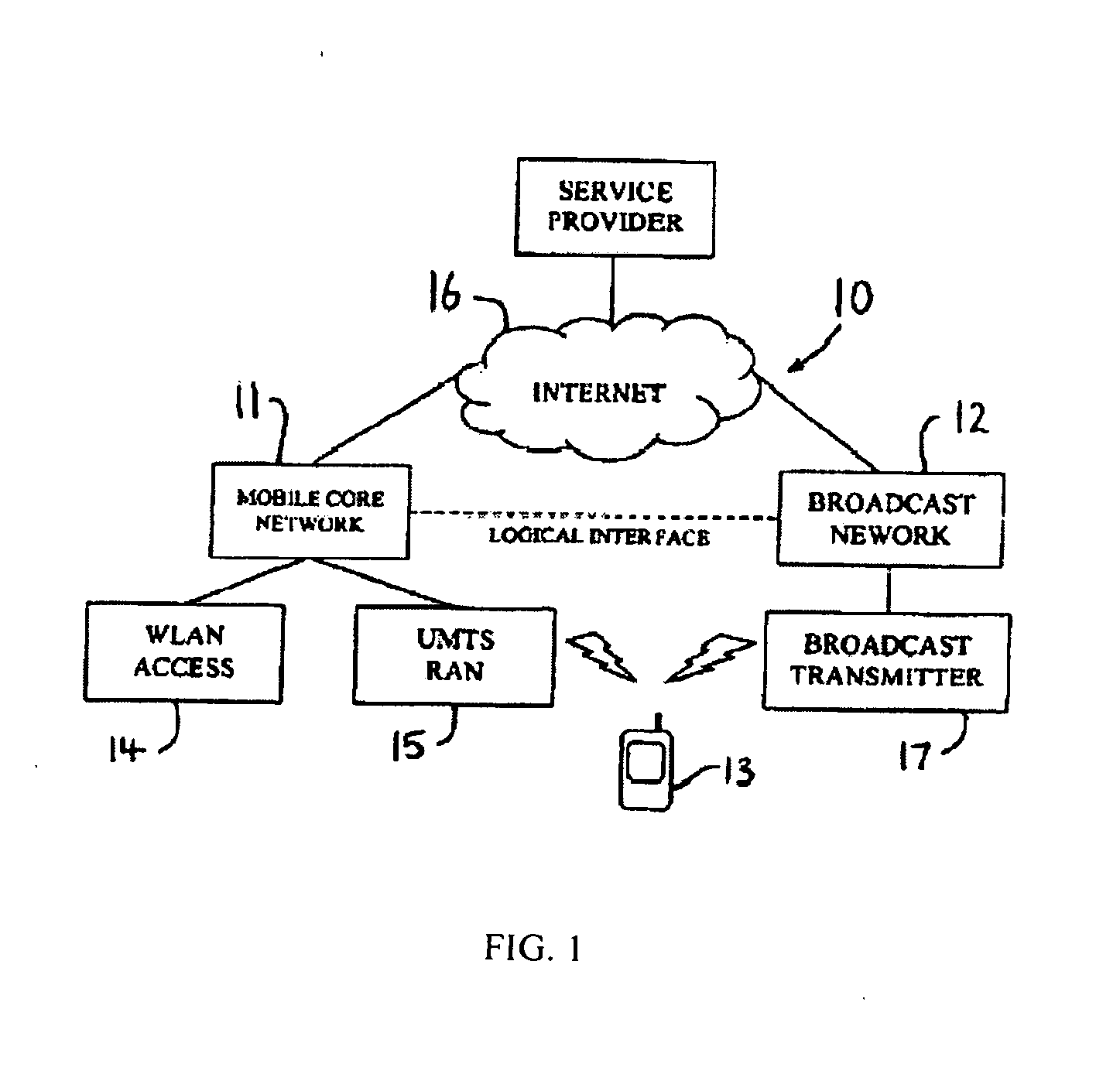
[0070] Referring to FIG. 1 a heterogeneous network generally identified by reference numeral 10 comprises a mobile network 11 and a broadcast network 12. Each of the two networks 11, 12 is under a different administrative domain and they are heterogeneous i.e. the protocols for access, transmission and / or handling of data is different between the networks. A Multi-mode Mobile Terminal (MMT) 13 has interfaces (or a single re-configurable interface) for accessing both of the networks 11, 12. The mobile network 11 is the home radio communication network of the MMT 13 i.e. that network providing a permanent point of contact for the MMT 13 e.g. by telephone number, network layer address (e.g. IP address) and may also be that network responsible for Authentication, Authorisation and Accounting (AAA), billing the user and storing user profiles for example. The broadcast network 12 may be considered a foreign radio communication network of the MMT 13 as it may only be used occasionally by t...


PUM


Abstract

A method of discovering multi-mode mobile terminals (13) in a heterogeneous network environment, each multi-mode mobile terminal (13) having at least one interface for sending packet data to and / or receiving packet data from a home radio communication network (11) and a foreign radio communication network (12), said home radio communication network having a different access technology from said foreign radio communication network, each multi-mode mobile terminal (13) performing the steps of: (a) listening to said foreign radio communication network (12); (b) receiving and storing a foreign network indicator for indicating presence of said foreign radio communication network (12); and (c) transmitting said foreign network indicator to said home radio communication network (11); whereby said home radio communication network (11) may store a database comprising a mapping between a multi-mode mobile terminal identity, a home network indicator and a foreign network indicator, to facilitate interworking of said home and foreign radio communication networks.

Description

CROSS-REFERENCE TO RELATED APPLICATIONS [0001] Priority is claimed under 35 U.S.C. §119 from UK Patent Application No. 0501200.0 filed Jan. 21st 2005, the disclosure of which is incorporated herein in its entirety by reference. US GOVERNMENT RIGHTS [0002] Not applicable. FIELD OF THE INVENTION [0003] The present invention relates to a method of discovering multi-mode mobile terminals in a heterogeneous network environment, to a radio communication network, to a computer program, to a computer program product and to a multi-mode mobile terminal. BACKGROUND OF THE PRESENT INVENTION [0004] The packet-switched domain of a radio communication network provides access for mobile terminals to external packet data networks such as the Internet; coverage is usually provided by means of a cellular structure. As mobile terminals move with the cellular coverage area the mobile terminals must be handed over from cell to cell if a session is to be preserved, each handover known as a horizontal han...

Claims


Application Information

Patent Timeline
Patent Type & Authority Applications(United States)
IPC IPC(8): H04M1/00H04L12/54H04W8/08H04W8/12H04W36/14H04W48/16H04W48/18H04W88/06
CPCH04L47/15H04L47/767H04L47/824H04L47/829H04W8/08H04W8/12H04W36/0061H04W36/165H04W48/16H04W48/18H04W88/06H04L47/70H04W36/0007H04W36/0009H04W28/0226H04W28/08H04W36/144H04W8/04
Inventor AGHVAMI, ABDOLPANGALOS, PAULHOLLAND, OLIVER
Owner DOLBY LAB LICENSING CORP
Learn More