
Fiber-reinforced resin composition for parts of air intake system of internal combustion engine

a technology of fiber reinforced resin and intake system, which is applied in the direction of machines/engines, combustion-air/fuel-air treatment, inorganic insulators, etc., can solve the problems of having to be accompanied by a problem of weight increase in parts, intake noise may be caused by intake system parts, etc., to reduce the specific gravity of parts, the effect of reducing the flexural elasticity modulus of the intake system

Active Publication Date: 2006-07-27
TOYO ROKI MFG CO LTD +1
View PDF2 Cites 2 Cited by
  • Summary
  • Abstract
  • Description
  • Claims
  • Application Information

AI Technical Summary

Benefits of technology

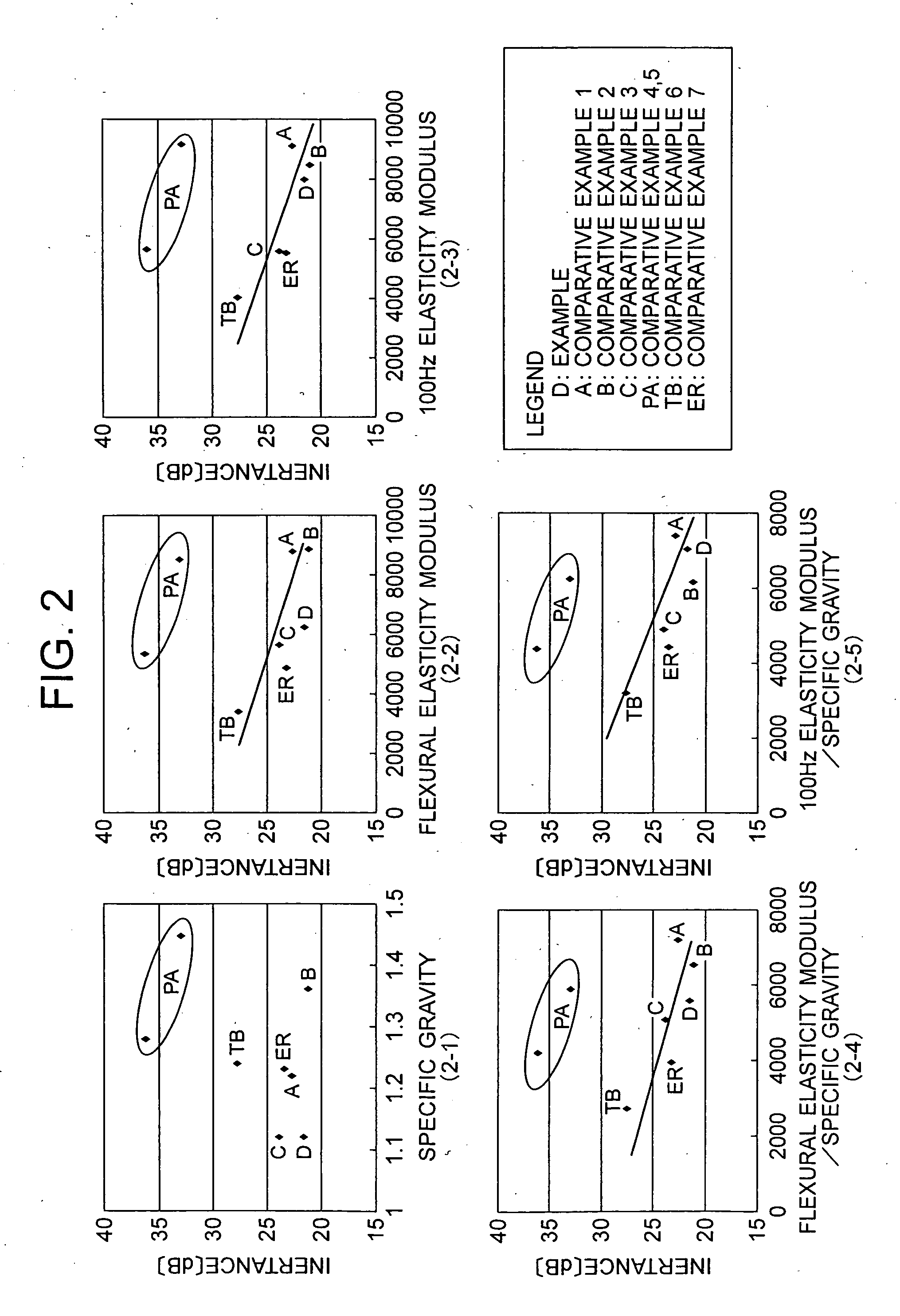
[0010] According to the present invention, a fiber reinforced resin composition for parts of intake system on the internal combustion engine can be obtained which is able to heighten the flexural elasticity modulus of the intake system's parts and reduce the specific gravity of the parts. Consequently, in the intake system's parts, the intake noise can be reduced without suffering from a weight increase.
[0011] Moreover, when the composition according to this invention is used with the aim of getting the same inertance with that of which the prior resin composition for intake system's parts is used, the producted article can have a lower specific gravity and a thinner thickness, and thus realize a weight loss.

Problems solved by technology

When the internal combustion engine is run and thus air is led into the internal combustion, an intake noise may be caused by the intake system's parts.
However, such a technique is obliged to be accompanied with a problem of weight increase in the parts.

Method used


Image

  • Fiber-reinforced resin composition for parts of air intake system of internal combustion engine
  • Fiber-reinforced resin composition for parts of air intake system of internal combustion engine
  • Fiber-reinforced resin composition for parts of air intake system of internal combustion engine

Examples


examples

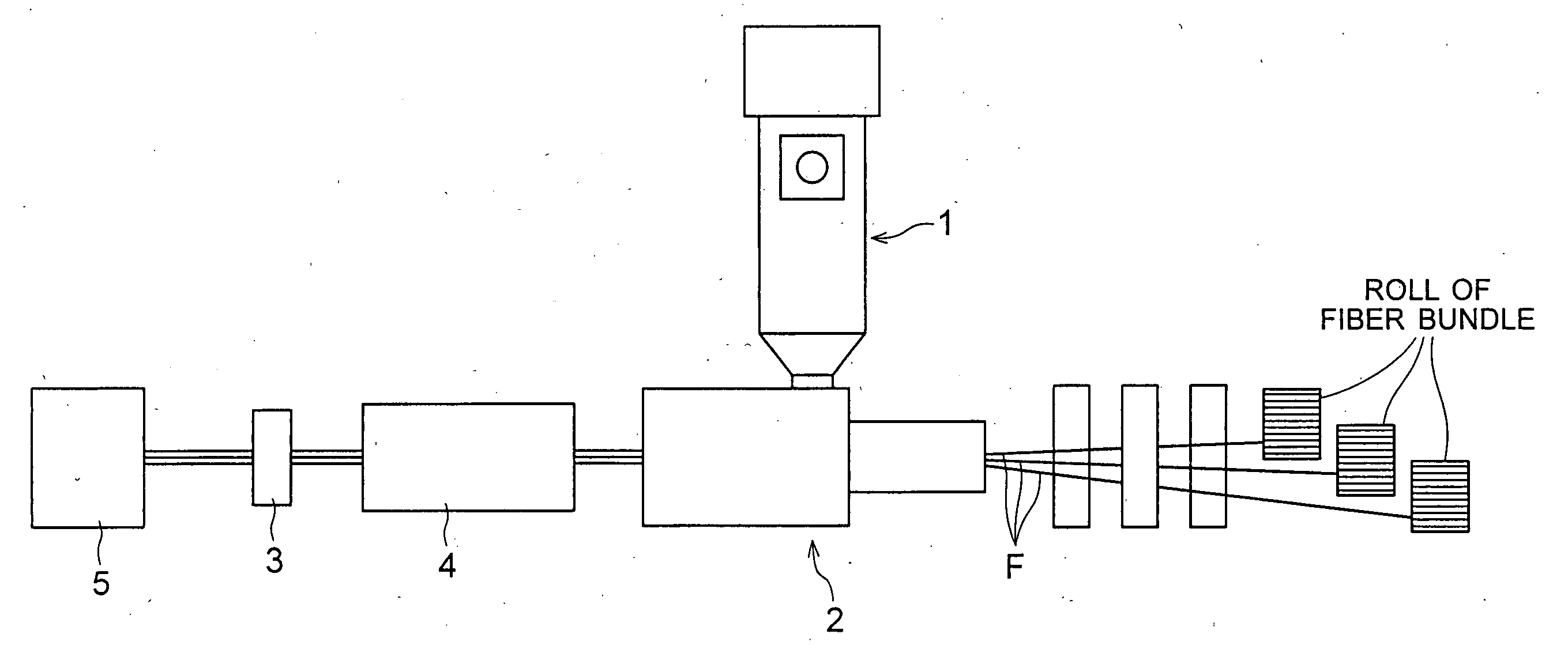
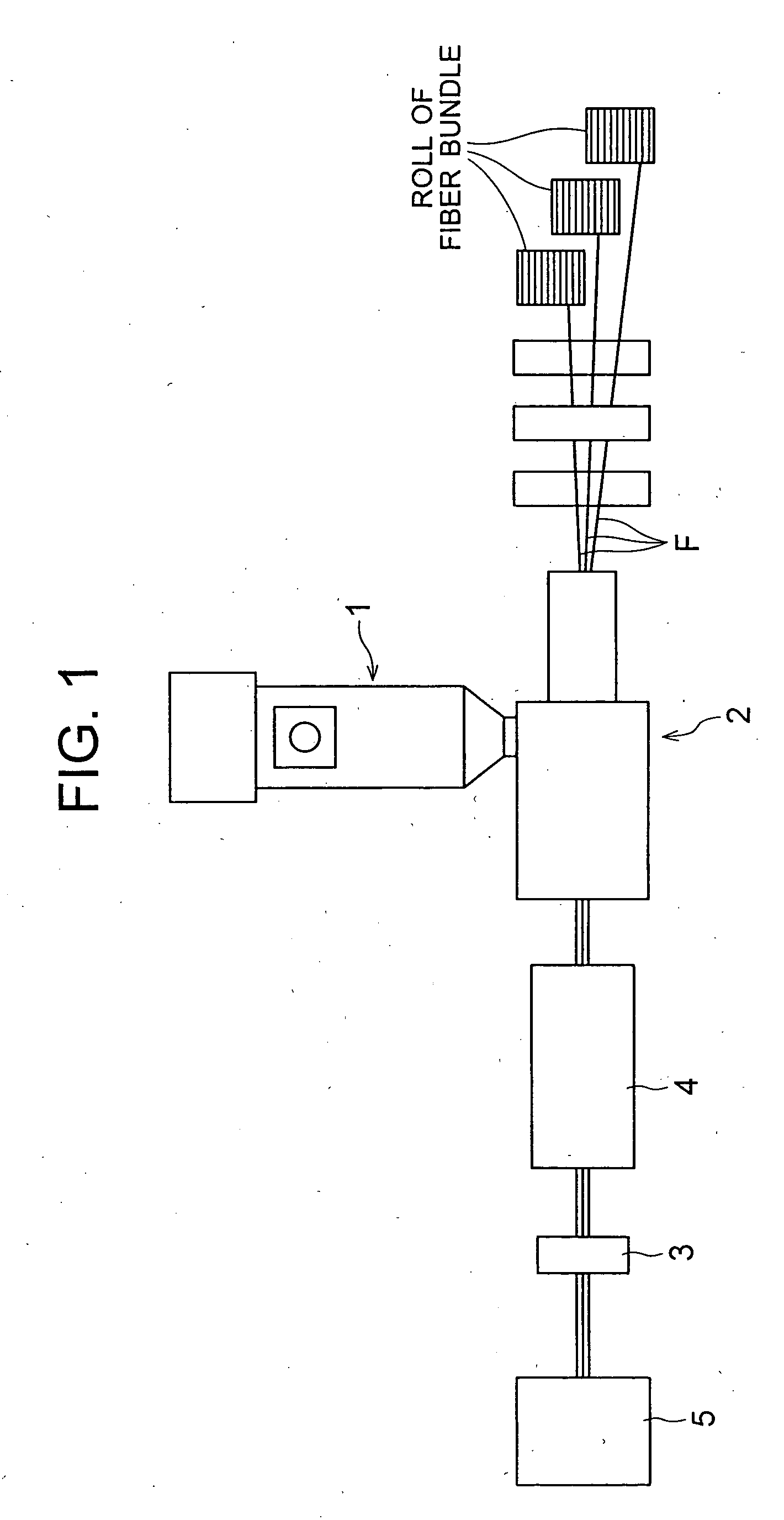
[0037] The fiber reinforced resin composition was prepared using the pellet manufacturing machine in FIG. 1.

[0038] Manufacturing Conditions [0039] Die: It was attached at the tip of an extruder of diameter 50 mm, and four rods were arranged as a straight line in the impregnating section. [0040] Fiber diameter: Glass roving was used which was bundled 170 glass fibers each having 16 ,,m in fiber diameter, the glass fibers being surface-treated in advance with amino silane. [0041] Preheating temperature: 200° C. [0042] Thermoplastic resin: block polypropylene of MFR50+carboxylic acid modified polypropylene. [0043] Melting temperature: 290° C. [0044] Rods: four rods, each having 6 mm(diameter)×3 mm(length).

[0045] Under the above-mentioned conditions, while amount of the fiber bundle was regulated with tension rolls, the glass roving was provided into the die in order to subject it to impregnation. Thereafter, it was pulled out from the die, cooled, and palletized in order to prepare a...


PUM

PropertyMeasurementUnit
Frequencyaaaaaaaaaa
temperatureaaaaaaaaaa
Tcaaaaaaaaaa

Abstract

Main object is to provide a composition for parts of the intake system, which is capable of enhancing the flexural elasticity modulus of the parts of the intake system and reducing the specific gravity of the parts. Disclosed is a fiber reinforced resin composition for parts of intake system on the internal combustion engine comprising a block polypropylene type resin which has a MFR in the range of 40-70 g / 10 minutes (at 230° C. and under a load of 2.16 kg) and which is in the range of 60-80% by weight of the composition, and glass fibers and mica the total of which are in the range of 20-40% by weight of the composition.

Description

TECHNICAL FIELD [0001] The present invention relates to a fiber reinforced resin composition for parts of intake system on the internal combustion engine. BACKGROUND ART [0002] In the intake system of the internal combustion engine, provided are an air duct constituting an intake channel of the internal combustion engine, a resonater or a side branch which is provided in the intake channel of the internal combustion engine and functions for reducing intake noise, and an air cleaner which collects dusts in the intake channel of the internal combustion engine. [0003] When the internal combustion engine is run and thus air is led into the internal combustion, an intake noise may be caused by the intake system's parts. In order to reduce the intake noise, a technique of enhancing the flexural elasticity modulus of the parts and thickening the thickness of the parts has been adapted conventionally. For example, to use a resin composition which is composed of polypropylene resin and talc ...

Claims


Application Information

Patent Timeline
Patent Type & Authority Applications(United States)
IPC IPC(8): C08K3/34C08K7/14C08L53/00F02M35/10F02M35/104
CPCC08L53/00F02M35/10321F02M35/10347
Inventor MATSUMOTO, TAKETOSHISUZUKI, JUNIWASHITA, TOHRUSUGAWARA, MINORU
Owner TOYO ROKI MFG CO LTD
Learn More