Bone implant, in particular, an inter-vertebral implant

a technology of bone implants and implants, which is applied in the field of bone implants, can solve the problems of easy leakage of filling and inability to allow optimal bone tissue growth, and achieve the effect of low water absorption

Inactive Publication Date: 2006-07-27
DEPUY SYNTHES PROD INC
View PDF14 Cites 122 Cited by
  • Summary
  • Abstract
  • Description
  • Claims
  • Application Information

AI Technical Summary

Benefits of technology

[0004] The bone implant according to the present invention is directed to an inter-vertebral implant comprising a front section, a back section, two lateral sections which define a cylindrical or central axis, and a substantially hollow interior chamber, each section having a superior and inferior vertebral contacting surface. The implant may be subdivided by at least two partitions that run essentially parallel to the cylindrical axis and connect the front section to the rear section of the sleeve so as to further define superior and inferior support areas. The implant may be made from radiation-permeable material, the radiation-permeable material exhibits low water absorption.
[0007] In another embodiment of the bone implant, the ratio V:v between the total volume V of the bone implant and the volume v of the hollow body is 2.1. Moreover, the hollow body may be at least partially filled with a material made of calcium phosphate, preferably hydroxyapatite or alternatively tricalcium phosphate. In addition, the body, may be at least partially filled with material made of calcium sulfate, demineralized bone, autologous bone, or coralline substances. In another embodiment, the hollow body may be at least partially filled with an X-ray-opaque filler. The X-ray-opaque filler being made of a resorbable, preferably porous polymer. In order to design the filler to be X-ray-opaque, contrast medium may be added to the polymer. For PLA a marker, for example, such as zirconium dioxide, may be added, and barium sulfate may be admixed with PEEK. In another preferred embodiment, the perforations of the partitions, lateral sections or both may be filled with the X-ray-opaque filler thereby preventing the filler from falling out.

Problems solved by technology

Some of the disadvantages of bone implants known in the art are that: (i) the smooth surfaces of the top and bottom surface areas of the implant or those that are equipped with macroscopic serrations in contact with the base plates of the adjacent vertebrae, do not permit an optimal bone tissue growth; and (ii) where any bone growth filler is located in the hollow body of the implant, the filling easily comes out because of the smooth inner walls of the hollow body of the implant.

Method used


Image

  • Bone implant, in particular, an inter-vertebral implant
  • Bone implant, in particular, an inter-vertebral implant

Examples


Embodiment Construction

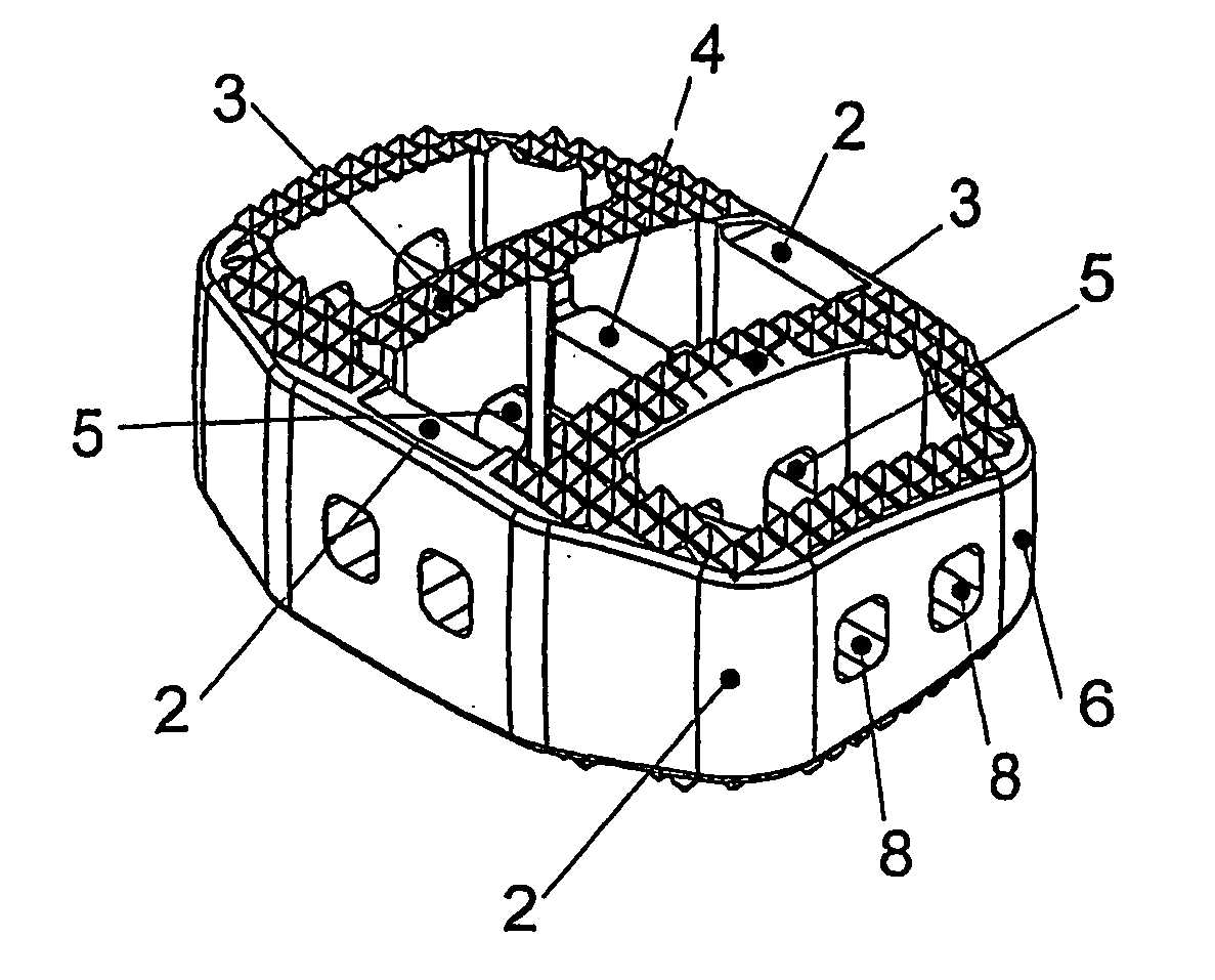
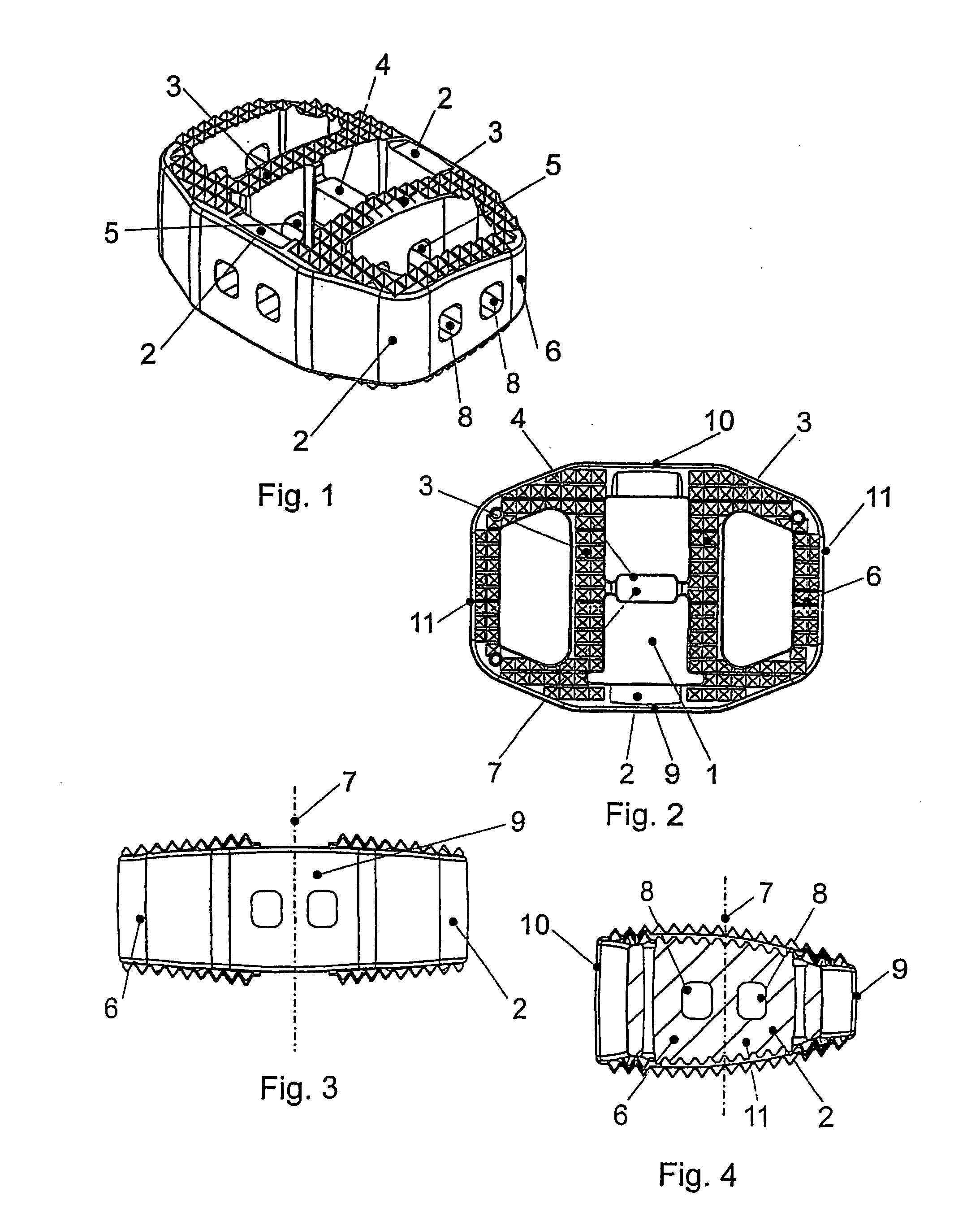
[0017] Referring to FIGS. 1 through 4, there is shown an inter-vertebral implant configured for insertion between the adjacent vertebral endplates and permitting growth of an osseous structure through the implant. The inter-vertebral implant may be a generally annular or circular shaped hollow body 1 comprising a mantle or sleeve 6 defining a hollow cylindrical or cone section which has a front section 9, a rear section 10, and two lateral sections 11, and further defines a cylindrical or central axis 7. The hollow body 1 may be divided into chambers by at least two intermediate walls 3 running essentially or substantially parallel to cylindrical axis 7. The intermediate walls or partitions 3 connect front section 9 with back or rear section 10 of the sleeve 6, and may be supported, interconnected and spaced with respect to one another by at least one cross brace or strut 4. Intermediate walls 3 increase the support areas on the neighboring vertebral body endplates, thereby reducing...


PUM

PropertyMeasurementUnit
areaaaaaaaaaaa
surface areaaaaaaaaaaa
areaaaaaaaaaaa

Abstract

A bone implant and the method of manufacturing thereof, the bone implant, in particular an inter-vertebral implant, made of a radiation-permeable material. The inter-vertebral implant defining a surface and comprising a front section, a back section, two lateral sections defining a central axis, and a substantially hollow interior chamber, each section having a superior and inferior vertebral contacting surface. The hollow chamber is subdivided by at least two partitions running essentially parallel to the central axis and which connect the front section to the back section.

Description

CROSS-REFERENCE TO RELATED APPLICATIONS [0001] This application is a continuation of application Ser. No. 10 / 629,694, filed Jul. 30, 2003, which is a continuation of International Patent Application No. PCT / CH01 / 00069, filed Jan. 30, 2001, the entire contents of each of which are expressly incorporated herein by reference thereto.BACKGROUND OF THE INVENTION [0002] The present invention is directed to a bone implant, in particular an inter-vertebral implant as well as a method for producing the same. [0003] Some of the disadvantages of bone implants known in the art are that: (i) the smooth surfaces of the top and bottom surface areas of the implant or those that are equipped with macroscopic serrations in contact with the base plates of the adjacent vertebrae, do not permit an optimal bone tissue growth; and (ii) where any bone growth filler is located in the hollow body of the implant, the filling easily comes out because of the smooth inner walls of the hollow body of the implant....

Claims


Application Information

Patent Timeline
Patent Type & Authority Applications(United States)
IPC IPC(8): A61F2/44A61F2/00A61F2/28A61F2/30
CPCA61F2/30771A61F2/30965A61F2/442A61F2/4455A61F2002/2835A61F2002/3008A61F2002/30777A61F2002/30785A61F2002/30789A61F2002/30843A61F2002/30957A61F2002/4475A61F2250/0098A61F2310/00239A61F2310/00293A61F2310/00407A61F2310/00562A61F2310/00568A61F2310/00796A61F2002/30593A61F2/44
Inventor MATHYS, ROBERT JR.LECHMANN, BEATGASSER, BEAT
Owner DEPUY SYNTHES PROD INC
Why Eureka
Try Eureka