Ball screw with a changeable oil-storage unit

a technology of oil storage unit and ball screw, which is applied in the direction of gear lubrication/cooling, toothed gearings, and nut and screw shaft friction, etc., can solve the problems of uneven lubrication of elements, increase in friction between nut and screw shaft, and accelerate the abrasion of ball screws

a technology of oil storage unit and ball screw, which is applied in the direction of gear lubrication/cooling, toothed gearings, and nut and screw shaft friction, etc., can solve the problems of uneven lubrication of elements, increase in friction between nut and screw shaft, and accelerate the abrasion of ball screws

US20060169075A1Inactive Publication Date: 2006-08-03HIWIN TECH

Image

  • Ball screw with a changeable oil-storage unit
  • Ball screw with a changeable oil-storage unit
  • Ball screw with a changeable oil-storage unit

Examples


Embodiment Construction

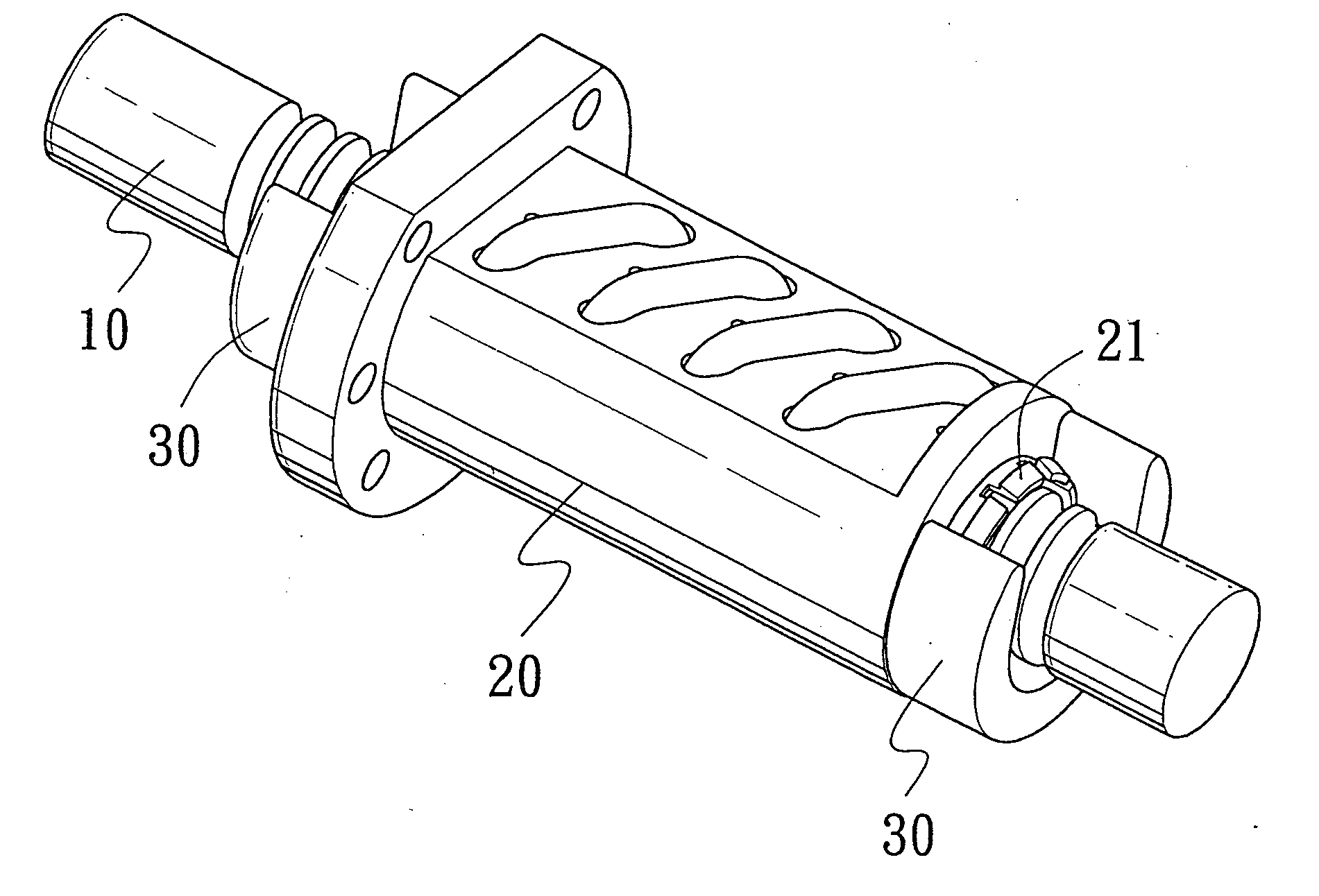
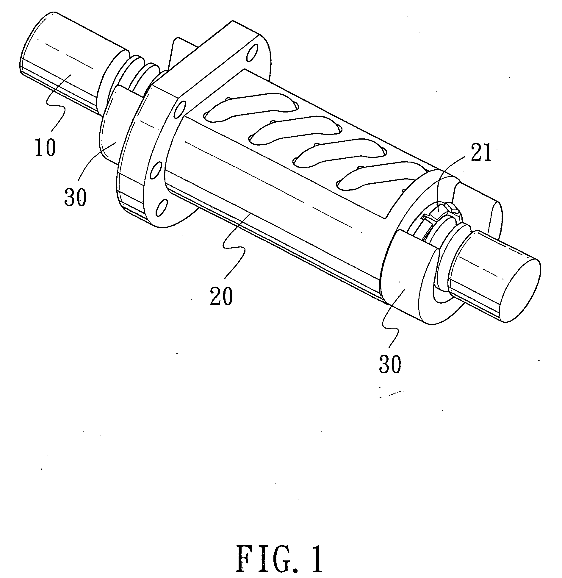
[0024]FIG. 1 shows a ball screw with a changeable oil-storage unit in accordance with a first preferred embodiment of the present invention, in which, a screw shaft 10 is a column-shaped member provided at its outer surface with a plurality of teeth. The nut 20 is mounted on the screw shaft 10 and is provided with hooks 21 at both ends thereof for retaining an oil-storage unit 30. The ball screw can be lubricated automatically when the lubricating oil in the oil-storage unit flows to the nut 20. The hooks 21 can be circular-shaped or any other shapes as along as it has a hooking function.

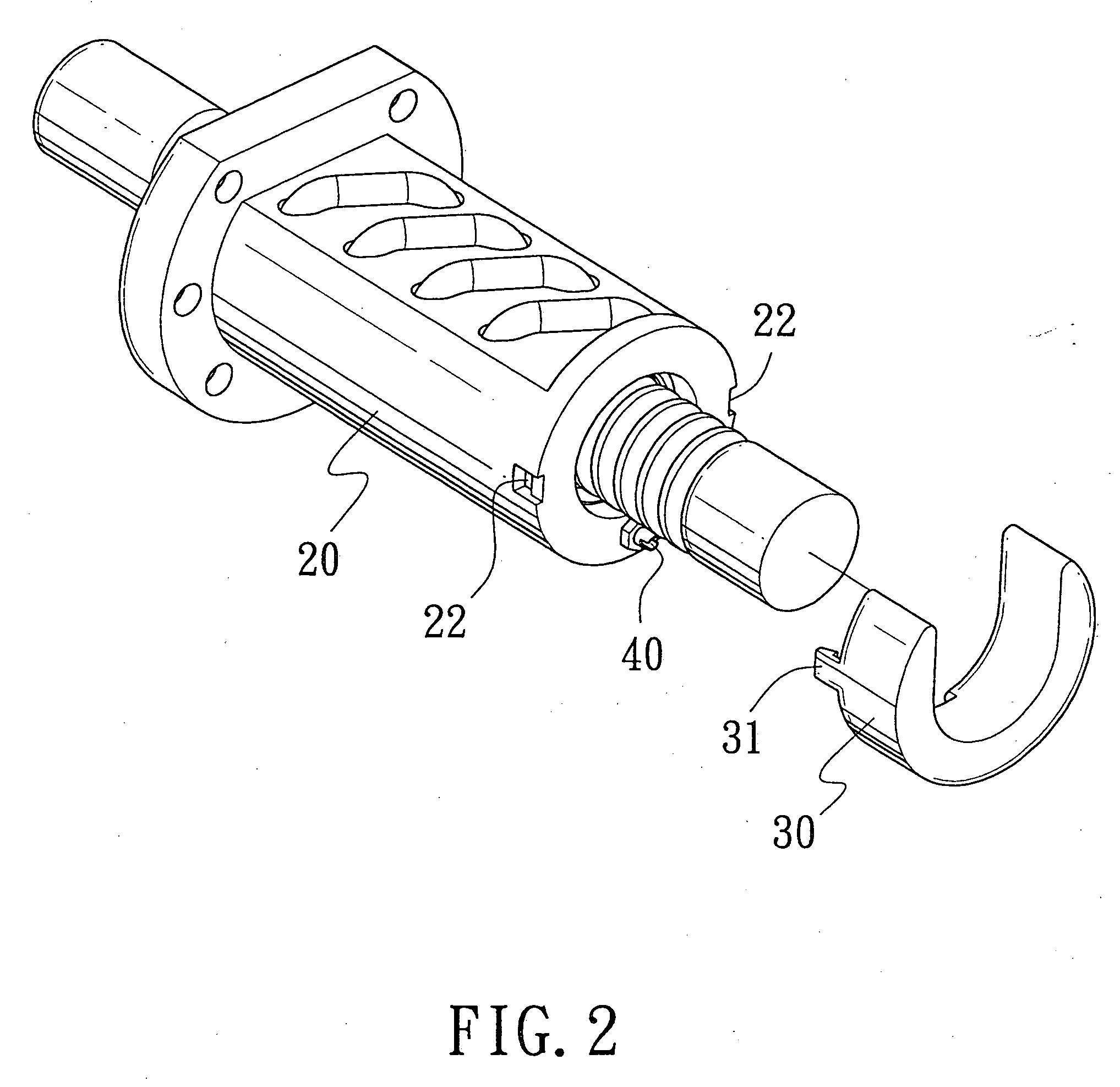
[0025]FIG. 2 shows a ball screw with a changeable oil-storage unit in accordance with a second preferred embodiment of the present invention; FIG. 3 is an enlarged view of the oil-storage unit on the ball screw of FIG. 2. The oil-storage unit 30 is U-shaped in response to the shape of the screw shaft 20 and is provided with hooks 31 and an oil feeding hole 32. On the outer surface of the screw shaf...


PUM


Abstract

A ball screw with a changeable oil-storage unit comprises: a screw shaft, a nut mounted on the screw shaft, a plurality of rolling elements, the nut defined with oil filler hole; an oil-storage unit having an oil feeding hole and an oil-storage space; a connector having a through hole and two connecting portions for mating with the oil filler hole of the nut and the oil feeding hole of the oil-storage space, respectively; one of the connecting portions has a tongue and groove arrangement, so that the through hole of the connector is connected to the oil filler hole of the nut and the oil feeding hole of the oil-storage space, forming an oil route that is used to provide lubricating oil for the ball screw.

Description

BACKGROUND OF THE INVENTION [0001] 1. Field of the Invention [0002] The present invention relates to a ball screw with a changeable oil-storage unit which enables the oil-storage unit to be assembled to or disassembled away from the screw shaft quickly and easily, thus providing a long lasting self-lubrication function for the ball screw. [0003] 2. Description of the Prior Arts [0004] Ball screw is such a machine that is used for motion transmission by taking use of the relative motion between its nut and screw shaft, the movement of the nut is realized by the rolling motion of the rolling elements between the nut and the screw shaft, so that the ball screw has a high efficiency of mechanical transmission. However, if the ball screw has not been lubricated enough for a long period of time, it may result in an increase in friction between the nut and the screw shaft, thus accelerating the abrasion of the ball screw. Hence, self lubricating function of a linear guideway has become mor...

Claims


Application Information

Patent Timeline
03 Aug 2006
Publication
US20060169075A1
IPC
F16H27/02; F16H25/22; F16H57/04
CPC
F16H25/2204; Y10T74/18744; F16H57/0497; F16H57/045
Inventors
CHUO, YUNG-TSAI