Golf car having disk brakes and flexible brake lines

a technology of flexible brake lines and disc brakes, which is applied in the direction of brake systems, mechanical equipment, transportation and packaging, etc., can solve the problems of reducing the comfort of the brake pedal, and reducing the degree of chaffing, so as to reduce the amount of fluid leakage and plastic deformation, prevent or at least minimize the damage caused by chaffing, and improve the resistance to corrosion

Inactive Publication Date: 2006-08-03
LANG JOSEPH A +4
View PDF40 Cites 21 Cited by
  • Summary
  • Abstract
  • Description
  • Claims
  • Application Information

AI Technical Summary

Benefits of technology

[0016] The present invention is directed to a golf car including a frame supported on a plurality of wheels. A prime mover provides driving force to selected wheels to displace the golf car. The golf car also includes an operator or passenger area supported by the frame and an integrated brake pedal and accelerator pedal assembly. A hydraulically operated brake system receives input from the brake pedal and generates an output from a hydraulic system to control a hydraulically operated braking device. The brake system operates in a normal mode by partially depressing the brake pedal, and the brake system operates in a parking mode by depressing the brake pedal further. When the brake system is in the parking mode, the brake system may be released by depressing either the brake pedal or accelerator pedal. A brake line is fluidly coupled between the braking device and the hydraulic system for carrying the hydraulic fluid under pressure. The brake line includes a flexible inner member and a braided outer member, which is sized to closely conformed to an outer shape of the flexible inner member. The braided outer member generally prevents radial expansion of the flexible inner member to minimize fluid leak and plastic deformation of the brake line and improves resistance to corrosion. The braided outer member further prevents or at least minimizes damage caused by chaffing.

Problems solved by technology

In some golf cars, the first detent position does not apply sufficient braking force to maintain the golf car in a stationary position.
However, because each detent position often generates an audible click, an operator may assume that the parking brake has been sufficiently engaged when the parking brake has yet to be sufficiently engaged.
When disengaging the parking brake, such brake systems often generate a particularly loud, audible pop which can be somewhat distracting to the operator.
Such radial expansion of the rubber line when hydraulic pressure is applied may lead to “softening” of the brake pedal feel, which is disadvantage in most applications.
This expansion of the rubber line when hydraulic pressure is applied is particularly disadvantage in golf car applications.
In a system where hydraulic pressure is used for long term parking function a constant high-pressure hydraulic Therefore, when a golf car is stored for many months with the parking brake engaged, this high hydraulic pressure may result in plastic deformation of a conventional hydraulic brake line assembly.
Deformation of the brake line may then lead to reduced brake effectiveness, decreased system life, and / or “softening” of the brake pedal feel.
Still further, golf car applications are often faced with a number of unique problems, which are generally not found in conventional automobile applications.
For example, as mentioned above, hydraulic brake systems in golf cars often are stored under pressure for several months, which may lead to plastic deformation of the brake lines and the associated reduction in useful life and brake effectiveness.
Furthermore, many golf cars operate in severe corrosive environments.
All of these contribute to the corrosion of metallic components on the golf cars, such as metal brake lines and fasteners.
The acid from the batteries, in both liquid and vapor form, tend to accelerate the corrosion of metals positioned nearby.
As can be appreciated, these caustic elements and battery acid may lead to failures in conventional rigid metal brake lines and the associated fasteners.
Conventional rigid metal lines limit the routing options, since their inflexibility prohibits them from being threaded through and around chassis and frame features.

Method used


Image

  • Golf car having disk brakes and flexible brake lines
  • Golf car having disk brakes and flexible brake lines
  • Golf car having disk brakes and flexible brake lines

Examples


Embodiment Construction

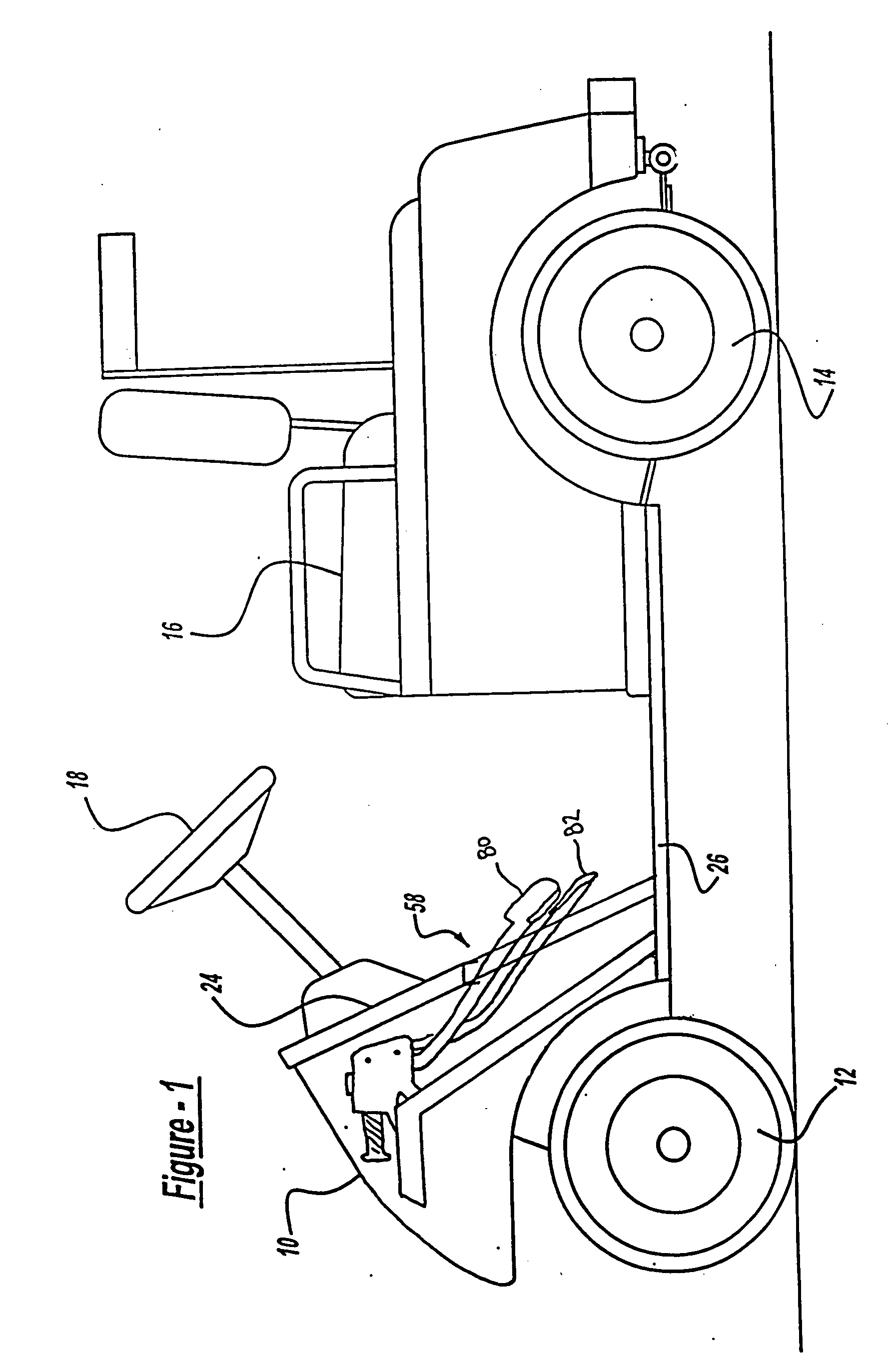
[0037]FIG. 1 depicts a golf car 10 having a brake system arranged in accordance with the principles of the present invention. Golf car 10 includes a pair of front wheels 12 and a pair of rear wheels 14. Rear wheels 14 preferably operate as steering wheels to control the direction of travel of golf car 10. Rear wheels 14 preferably function as drive wheels for propelling golf car 10.

[0038] Golf car 10 includes a seat 16 which preferably accommodates a driver and a passenger. Golf car 10 also includes a steering wheel 18 which controls the direction of front wheels 12. An accelerator pedal 82 and a brake pedal 80 enable the operator to control acceleration and braking of golf car 10. Accelerator pedal 82 and brake pedal 80 preferably are suspended from support members which hang generally downwardly from underneath a front cowling 24, as will be described herein.

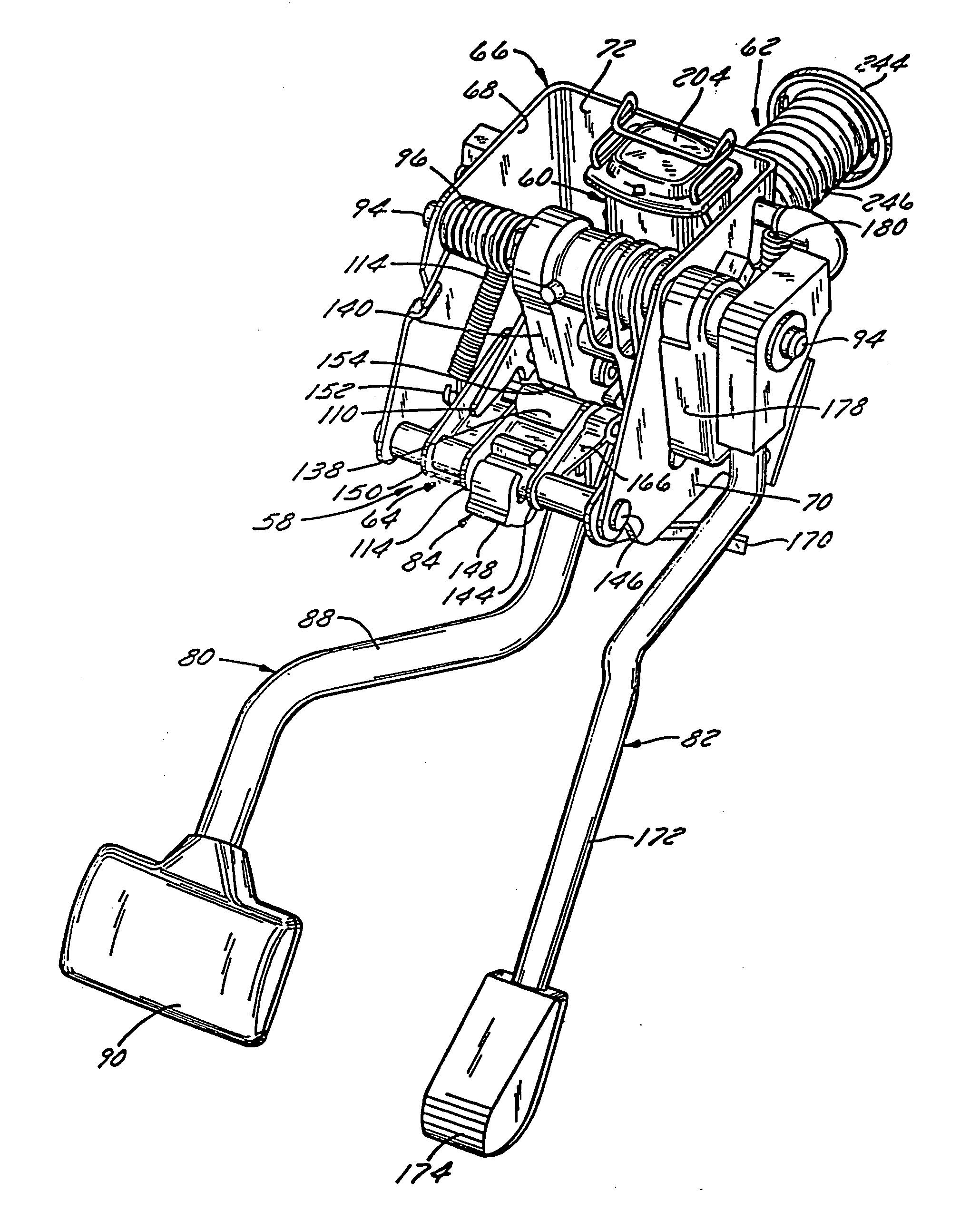
[0039] Still referring to FIG. 1, an entire brake actuator and release assembly 50 is configured as a modular unit mounted...


PUM


Abstract

A golf car having a hydraulic disk brake system responsive to hydraulic fluid pressure generated from a master cylinder. A brake pedal and associated linkage provides input to a master cylinder to generate a hydraulic fluid pressure to control a brake caliper assembly. A flexible brake line is fluidly coupled between the brake pedal and the disk brake system for carrying the hydraulic fluid. The brake line is comprised of a flexible inner member and a braided outer member. The brake pedal has a range of travel, where a first portion of the range defines a service mode of operation and a second portion of the range defines a parking mode of operation. In the parking mode of operation, the brake pedal and linkage engages a detent to maintain application of the brake to provide a parking mode of operation.

Description

CROSS REFERENCE TO RELATED APPLICATIONS [0001] This application is a continuation-in-part of U.S. patent application Ser. No. 10 / 087,461, filed on Mar. 1, 2002, and U.S. patent application Ser. No. 10 / 662,127, filed on Sep. 12, 2003. U.S. patent application Ser. No. 10 / 662,127 is a continuation of U.S. application Ser. No. 10 / 206,266, filed Jul. 26, 2002, which is a continuation of U.S. patent application Ser. No. 09 / 846,031, filed Apr. 30, 2001 (now U.S. Pat. No. 6,457,568) which is a continuation of U.S. patent application Ser. No. 09 / 517,302, filed Mar. 2, 2000 (now U.S. Pat. No. 6,223,865), which claims the benefit of priority of U.S. Provisional Application Ser. No. 60 / 122,405, filed Mar. 2, 1999, the entire contents of which are hereby expressly incorporated by reference into the present application.BACKGROUND [0002] 1. Technical Description [0003] The present invention relates generally to golf cars having disk brakes and, more particularly, to golf cars having hydraulically ...

Claims


Application Information

Patent Timeline
Patent Type & Authority Applications(United States)
IPC IPC(8): F16D65/00B60T17/04
CPCB60T7/045B60T11/10B60T17/04F16D55/228
Inventor LANG, JOSEPH A.LANG, SUSANREESE, TERRY LOUCRISCUOLO, JAMES M.BIGSBY, BRYAN D.
Owner LANG JOSEPH A
Why Eureka
Try Eureka