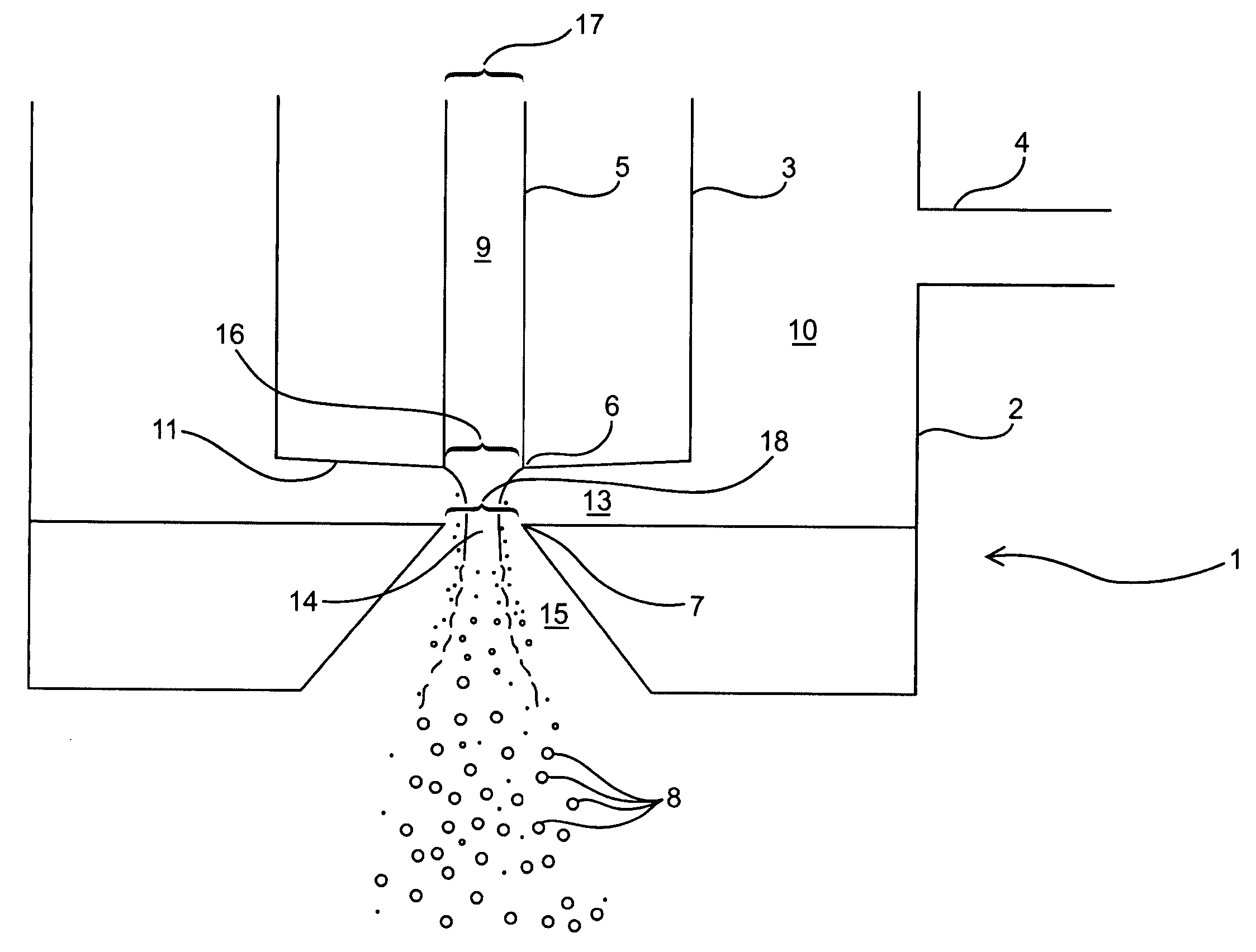
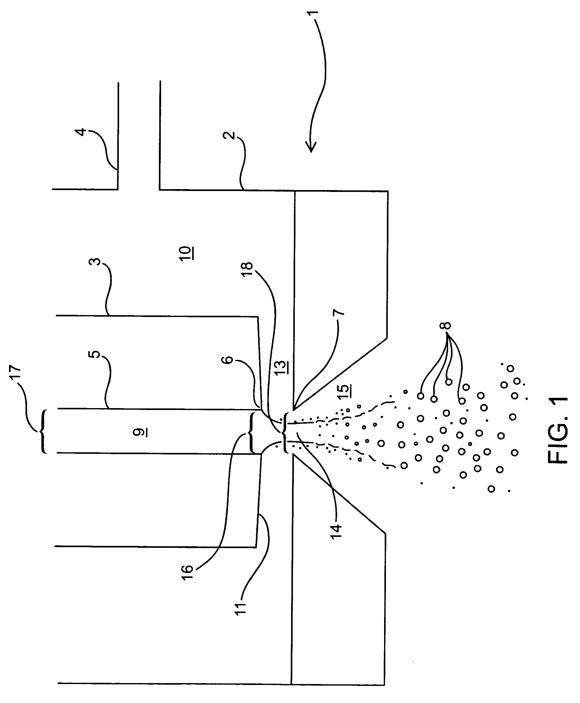
Aerosol created by directed flow of fluids and devices and methods for producing same
a technology of directed flow and fluids, applied in the direction of combustion types, combustion processes, burners, etc., can solve the problems of disadvantages of pneumatic atomizers, general low efficiency of energy transfer, and more expensive manufacturing
- Summary
- Abstract
- Description
- Claims
- Application Information
AI Technical Summary
Benefits of technology
Problems solved by technology
Method used
Image
Examples
examples
[0111] The following examples are put forth so as to provide those of ordinary skill in the art with a complete disclosure and description of how to make and use the present invention, and are not intended to limit the scope of what the inventors regard as their invention nor are they intended to represent that the experiments below are all or the only experiments performed. Efforts have been made to ensure accuracy with respect to numbers used (e.g. amounts, temperature, etc.) but some experimental errors and deviations should be accounted for. Unless indicated otherwise, parts are parts by weight, molecular weight is weight average molecular weight, temperature is in degrees Centigrade.
examples 1-5
[0112]FIGS. 6-12 show results for aerosols produced by methods of the present invention using dry air and dry nitrogen as second fluids 10, and a range of liquids as first fluids 9: distilled water, 2-propanol, 20% (v / v) by volume of ethanol in water (“20% EtOH”), and 0.1% weight in volume (w / v) Polysorbate-20 in distilled de-ionized water (“0.1% Tween”). Tests were performed in four separate experiments with different atomizers. The atomizers were of an axi-symmetric type and had dimensions as specified below in Table A for variables defined in FIGS. 4 and 5. Specifically, the pressure chamber discharge opening was conveniently created by drilling a straight-through hole through a plate of thickness T.
[0113] In experiments 1-4, the droplet size was determined by phase Doppler anemometry (Lefebvre 1989; Bayvel and Orzechowski 1993) along the axis of the aerosol plume a few centimeters downstream from the exit of the atomizer. This measurement technique led to notoriously low rates ...
example 6
[0129]FIGS. 10, 11, and 12 report results from a separate experiment in which the aerosol size distribution was carefully measured as a function of the distance between the first fluid supply means and the pressure chamber, H. Aerosol size distributions were measured outside the atomizer using a standard aerosol measurement technique called laser diffraction (using a Sympatec HELOS system). A device was designed having a configuration as that shown on FIG. 5. The geometric parameters for this system are recorded in the last line of TABLE A above. Measurements of the particle size distribution were made with de-ionized water as first fluid and dry nitrogen as second fluid, at a water flow rate of 35 ml / hr and a pressure in the pressure chamber measured upstream from channel 13 relative to the room into which the aerosol was discharged, of 10 bar. Presented are two statistics that define the particle size: d85 and GSD. d85 represents the diameter under which is represented 85% of the ...
PUM
 Abstract
Description
Claims
Application Information
 - R&D
- Intellectual Property
- Life Sciences
- Materials
- Tech Scout
- Unparalleled Data Quality
- Higher Quality Content
- 60% Fewer Hallucinations
Browse by: Latest US Patents, China's latest patents, Technical Efficacy Thesaurus, Application Domain, Technology Topic, Popular Technical Reports.
© 2025 PatSnap. All rights reserved.Legal|Privacy policy|Modern Slavery Act Transparency Statement|Sitemap|About US| Contact US: help@patsnap.com


