Data transmission system and data transmission method

a data transmission system and data technology, applied in data switching networks, data switching networks, frequency-division multiplexes, etc., can solve the problems of not being able unable to set a communication line for high-speed communication, and unable to transmit a large amount of data which requires a transmission rate more than the above transmission rate, etc., to achieve the effect of reducing the frequency band used

Inactive Publication Date: 2006-08-03
PANASONIC CORP
View PDF20 Cites 89 Cited by
  • Summary
  • Abstract
  • Description
  • Claims
  • Application Information

AI Technical Summary

Problems solved by technology

The conventional data transmission method in a transporting vehicle, however, was not able to transmit a large amount of data.
Therefore, a large amount of data which requires a transmission rate more than the above transmission rate was not able to be transmitted through an existing communication line.
In order to transmit a large amount of data, operation and costs for setting a communication line for high-speed communication which connects cars anew are required.
A large amount of data is also required to be transmitted with high speed and real time transmission between cars.
As such, a large amount of data has been required to be transmitted between cars.

Method used


Image

  • Data transmission system and data transmission method
  • Data transmission system and data transmission method
  • Data transmission system and data transmission method

Examples


first embodiment

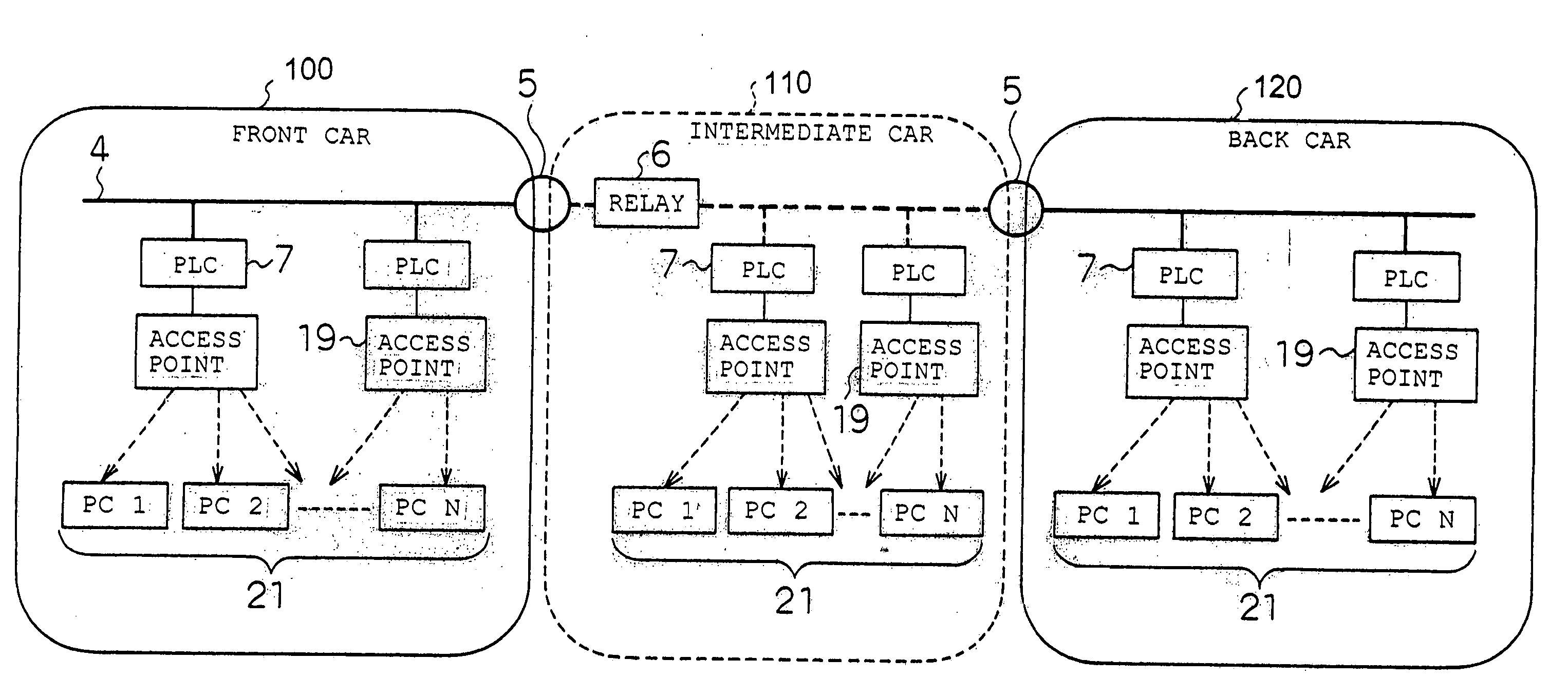
[0167]FIG. 1 is a schematic view showing a system configuration of a data transmission system between railway cars according to a first embodiment of the present invention.

[0168] In the data transmission system between railway cars, railway cars generally includes a front car 100, intermediate cars 110 consisting of some cars, and a back car 120 at the end. A laid line 4, which is represented as an electric wire for supplying power to each car, is connected through the cars via relays 6 placed near coupling sections 5 of the respective cars.

[0169] PLC (Power Line Communications) modems 7 are set on the laid line 4, which is represented as an electric wire drawn in the cars. Various terminals 8 are connected with the laid line 4 via the PLC modems 7. The various terminals 8 include a camera for taking a picture of passengers inside a car or on a platform or a flow of passengers in a station, a monitor for displaying an image taken by the camera, a Communication Control Unit as a so...

second embodiment

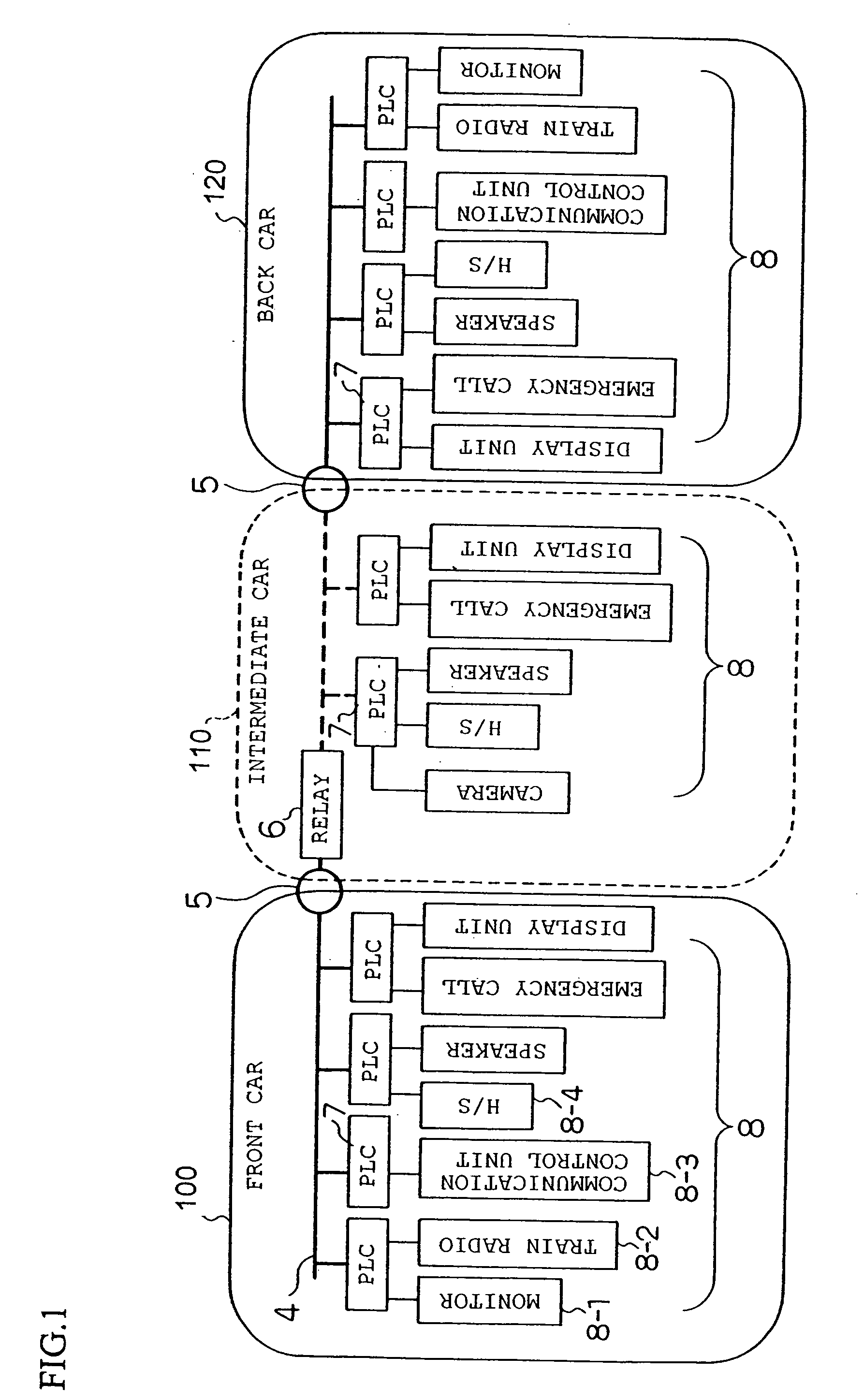
[0180]FIG. 2 is a schematic view showing a system configuration of a data transmission system between railway cars according to the second embodiment of the present invention.

[0181]FIG. 2 is different from FIG. 1 in that each terminal 9 is a broadband type terminal which requires higher speed higher bandwidth digital transmission than that of each terminal 8 of FIG. 1.

[0182] If a game device 9-2 for providing a motion picture is used as a terminal, the device requires several Mbps—dozens of Mbps band to provide a video game in a smooth moving picture for a passenger. Communication employing the PLC is said to enable data communication in several Mbps—hundreds Mbps. Thus, in view of this, the second embodiment can also be sufficient for a terminal which requires high speed and large amount of data for digital transmission.

[0183] Here, the PLC has reliability fulfilling a railway requirement of RAMS (Reliability, Availability, Maintainability, Safety). As the PLC has a feature of a...

third embodiment

[0189] Each of FIGS. 3 and 4 is a schematic view showing a system configuration of a data transmission system between railway cars according to a third embodiment of the present invention.

[0190] Each of FIGS. 3 and 4 shows a form of connecting, a conventional model existing car 10, which employs transmission for mainly transmitting analog signals, and a newly constructed car 11, which employs the above mentioned PLC.

[0191] In FIG. 3, a converter 12 and a PLC modem 7 are placed near a coupling section 5 of the newly constructed car 11. A conventional model laid line (communication line / control line / electric wire) 22 from the existing car 10 and a laid line (electric wire+PLC signal) 4 at the newly constructed car are connected at a connecting section 13.

[0192] A signal from the existing car 10 is outputted from a communication line or a control line and inputted into a converter 12. The inputted signal is converted at the converter 12 into digital data adequate for the PLC modem 7...


PUM


Abstract

The present invention includes an electric wire laid in cars, a PLC modem connected with each electric wire and a terminal connected with each PLC modem. The terminal can communicate through the electric wire by using the PLC modem. When the cars are coupled with each other, the electric wires are electrically connected with each other and a new address is allocated to a control unit which has a unique address provided for each terminal.

Description

BACKGROUND OF THE INVENTION [0001] 1. Field of the Invention [0002] The present invention relates to a data transmission system and a data transmission method for a transporting vehicle. The present invention relates to a data transmission system and a data transmission method between cars of a railway, a subway or the like, or inside a bus, an airplane, a ship or the like. [0003] Alternatively, the present invention relates to a system of transmitting data between rooms in a liner or the like. [0004] 2. Related Art of the Invention [0005] Various types of announcement on board a train or image information services using laid lines have been provided as a service inside cars of a railway, a subway or the like. For example, the services include an audio service on a train or image information service to announce “This train is going to set out **:** bounding for ***.” or “The next stop is ***.”, for example, by using a display device such as a liquid crystal panel or the like. Image ...

Claims


Application Information

Patent Timeline
Patent Type & Authority Applications(United States)
IPC IPC(8): H02J3/02B60L1/00H04L5/16G05B11/01G08B1/08
CPCB61L15/0036B61L15/0045B61L15/0072B61L15/009H04B3/548H04B2203/547H04L2012/40293
Inventor MORIMITSU, KAZUYAUBUKATA, MAKOTOMAEDA, TETSUHIROKIBA, MASAOKUROBE, AKIO
Owner PANASONIC CORP
Why Eureka
Try Eureka